Medium-Voltage Direct-Connect Energy Storage Solution (E4Matrix)
1. Industry Background and Pain Points
1.1 Industry Background
Against the backdrop of the dual-carbon strategy and the build-out of the new power system, storage power plants are moving from a "supporting role" to a "grid necessity". According to the National Energy Administration, cumulative installed new-type storage capacity exceeded 80 GW in 2025, with 2–4-hour medium-duration storage becoming the main growth driver. Yet two technical bottlenecks still limit large-scale deployment: energy conversion efficiency and single-point-failure risk.
1.2 Four Pain Points of Traditional Solutions
| Pain point | Traditional behaviour | Physical root cause |
|---|---|---|
| High no-load loss | PCS + step-up transformer run energised around the clock, losing 1%–2% | The core loss of a line-frequency transformer cannot be eliminated |
| Many conversion stages | Battery → PCS → transformer → grid: 4 conversion steps | 1%–3% loss accumulates at each stage |
| SOC imbalance | Depth of charge/discharge differs between battery clusters | Passive balancing relies on battery consistency |
| Single-point failure | One failed module in a cascaded H-bridge (CHB) design stops the plant | No redundant bypass capability |
1.3 Traditional vs. SST Direct Connection — the Physical Difference
Traditional approach: four power conversions, taxed at every step
In a traditional storage plant, the battery's DC must pass through four separate devices to reach the 10 kV grid — each stage is a "power tax":
| Step | Equipment | Current form | Loss at this stage | In plain terms |
|---|---|---|---|---|
| ① | DC/DC converter | Battery DC → DC busbar (step up/down) | ~2%–3% | "Straightens out" the battery voltage to what the PCS needs |
| ② | PCS (inverter) | DC → AC 0.4 kV | ~2% | Turns DC into AC so it can enter the grid |
| ③ | Step-up transformer | AC 0.4 kV → AC 10 kV | ~1%–2% | Steps low-voltage AC up to medium voltage for grid connection |
| ④ | Grid-connection switchgear | AC 10 kV onto the busbar | Negligible | The final gate |
Estimated total loss: ~2% + 2% + 1.5% when charging, the same again when discharging — round-trip loss of about 8%–11%.
SST direct-connect approach: one conversion, done in one step
The battery's DC passes through a single SST device straight to the 10 kV grid:
| Step | Equipment | Current form | Loss at this stage | In plain terms |
|---|---|---|---|---|
| ① | SST solid-state transformer | Battery DC → high-frequency AC → DC → AC 10 kV | ~1%–2% | "Step-up + inversion + isolation" all inside one box; a high-frequency transformer replaces the line-frequency one |
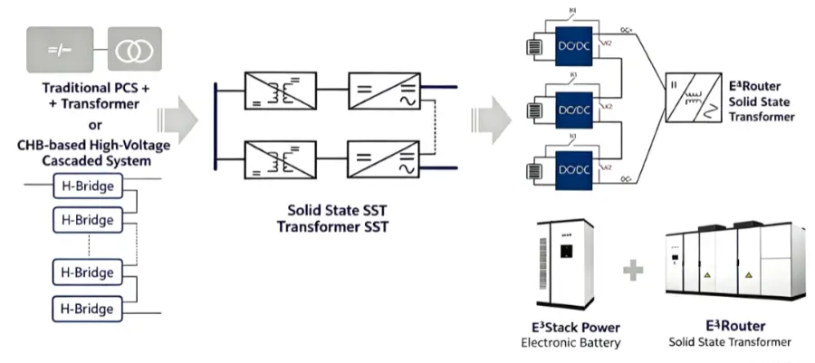
A one-picture view of the difference
Traditional (4 stages):
Battery → DC/DC → PCS → Step-up transformer → 10 kV
[2–3%] [2%] [1.5%] - transformer keeps idling and consuming power
SST direct-connect (1 stage):
Battery → [SST solid-state transformer] → 10 kV
Internal high-frequency transformer: small, efficient
Fully shut down in standby: zero loss
2. Solution Overview and Value Proposition
2.1 Solution Definition (BLUF)
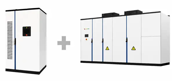
The SST medium-voltage direct-connect storage system (E4Matrix) uses the solid-state transformer as its core, replacing the traditional "PCS + step-up transformer" or cascaded H-bridge (CHB) architecture, so battery clusters connect directly to the 10 kV medium-voltage busbar. It delivers:
- Round-trip efficiency +2% (transformer no-load loss eliminated)
- Usable energy +6% (active SOC balancing)
- Single-point-failure loss of <0.1% (module-level redundant bypass)
- No no-load loss (the SST drops to zero loss when shut down)
2.2 Core Value Proposition
| Value dimension | Metric | vs. traditional |
|---|---|---|
| Energy efficiency | Round-trip efficiency +2% | ~8% more cycle energy recovered over a 20-year life |
| Usable capacity | SOC balancing +6% | 6% more energy released from the same capacity |
| Reliability | Single-point failure <0.1% | 100% loss on CHB cascade failure |
| Footprint | −30% | Step-up transformer and HV switchgear removed |
| Response speed | Millisecond level | No mechanical parts in power regulation |
3. System Architecture
3.1 System Topology (Layer by Layer)
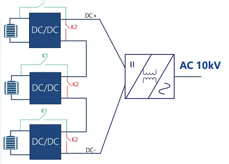
- Grid-connection layer: 10 kV AC medium-voltage busbar (dual-loop incoming) — grid-connection switch QF (opened for maintenance to form a visible gap), metering CT/PT (gateway metering), and protection devices (overcurrent / differential / undervoltage)
- Conversion layer: SST module group (N+1 redundancy) — module A (active), module B (active), module C (standby, automatically takes over on failure)
- Storage layer: battery-cluster group — Cluster 1 (LFP-280Ah), Cluster 2 (LFP-280Ah), Cluster 3 (LFP-280Ah)
- Management layer: EMS + BMS + fire-fighting controller + plant-level SCADA
| Layer | Composition | Power flow | Signal flow | Design rationale |
|---|---|---|---|---|
| ① Grid connection | 10 kV busbar, QF grid-connection switch, CT/PT metering, protection | Storage ↔ grid, bidirectional | Switch position → SCADA | The grid-connection switch is the physical safety boundary; opening it for maintenance creates a visible gap |
| ② Conversion | N+1 SST modules | 10 kV AC ↔ battery-side DC | EMS → SST power commands; SST → EMS status | N+1 redundancy: if any unit fails, the rest share the load automatically — no shutdown |
| ③ Storage | Battery clusters (LFP-280Ah) | Battery DC ↔ SST | BMS → EMS: SOC / temperature / voltage | Clusters are independent; energy is balanced between them through the SST |
| ④ Management | EMS + BMS + fire-fighting + SCADA | No power, information only | Whole-plant data aggregation | The brain: decides when to charge, how much, and which cluster gets more |
3.2 Three-Tier Architecture
| Tier | Component | Function | Redundancy |
|---|---|---|---|
| Interface tier | SST module (AC/DC + DC/DC) | Medium-voltage direct connection, bidirectional conversion, isolation | N+X hot standby |
| Storage tier | Battery cluster (LFP-280Ah cells) | Energy storage, SOC balancing | Cluster-level fuse protection |
| Management tier | BMS + EMS | Battery management, energy dispatch | Dual controllers in hot standby |
3.3 Inside the SST Module (Single Module in Three Stages)
Overall structure
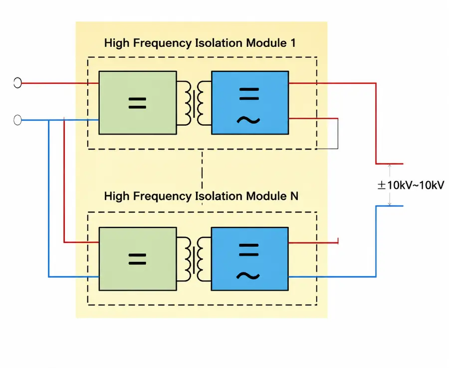
Power flow: 10 kV AC input → ① input rectifier stage → DC busbar → ② high-frequency isolation stage → low-voltage DC → ③ battery-interface stage → battery cluster
| Power stage | Function | Key components | In plain terms | Key physical parameters |
|---|---|---|---|---|
| ① Input rectifier stage | Converts 10 kV AC into a DC busbar | SiC MOSFET full bridge, soft-start resistor, EMI filter | "Straightens" the AC into DC | DC busbar ~12–15 kV; soft start limits closing inrush |
| ② High-frequency isolation stage | Step up/down + electrical isolation via a high-frequency transformer | SiC full bridge, high-frequency transformer (20 kHz+), resonant capacitor | The core technology: a small high-frequency transformer replaces the large line-frequency one — volume cut by 10x+ | Isolation withstand 42 kV; 20 kHz+ frequency (vs. 50 Hz line-frequency); ZVS soft switching at 98.5% efficiency |
| ③ Battery-interface stage | Converts the DC-busbar voltage to the 200–1000 V the battery needs, and controls charge/discharge | DC/DC converter, bidirectional IGBT/SiC | Like a voltage adapter that matches the battery voltage automatically | Stepless 200–1000 V output; current-control accuracy ±1% |
Why split it into three power stages?
- Separating ① and ②: the rectifier stage handles "AC → DC", while the isolation stage is dedicated to "voltage conversion + safety isolation". Splitting them keeps the voltage stress on each stage's devices reasonable and extends life.
- High-frequency transformer in ②: transformer size is inversely proportional to frequency — the higher the frequency, the smaller the core and windings at the same power. A 20 kHz transformer is roughly 90% smaller than a 50 Hz line-frequency unit — this is the physical basis of the SST's −30% footprint.
- SOC balancing in ③: the battery-interface stage can precisely control the charge/discharge current of each cluster, and the EMS uses this to "charge high-SOC clusters less, low-SOC clusters more" — active balancing.
4.1 Key Equipment Specifications
| Equipment | Model / specification | Key technical parameters |
|---|---|---|
| SST module | 10 kV direct-connect type | 1.0 / 1.25 / 1.5 MW per module; 98.5% efficiency; harmonics <1% |
| Battery cluster | LFP-280Ah | Nominal 3.2 V; cycle life >8,000; DOD 95% |
| BMS | Three-tier architecture | Active-balancing current ±2 A; sampling accuracy ±1 mV |
| EMS | Plant-level dispatch | Response <100 ms; supports IEC 60870-5-104 / DNP3.0 / Modbus |
| Fire-fighting | Perfluorohexanone | Cluster-level detection + suppression <10 s; re-ignition prevention |
4.2 System-Level Performance
| Parameter | Rating | Test / validation |
|---|---|---|
| Rated power | 1.2 MW (expandable to 5 MW) | GDS Chongqing station |
| Rated capacity | 2.4 MWh (expandable) | Same |
| Overall efficiency | ≥90% (AC side) | Measured by the Electric Power Research Institute |
| SOC balancing depth | 99% | Measured |
| Response time | <50 ms | Full-power regulation |
| Grid-connection standard | GB/T 34120 / GB/T 36276 | Type tested |
5. Technical Highlights and Physical Principles
5.1 Highlight 1: Zero No-Load Loss
- Physical principle: in the traditional approach, the step-up transformer produces core (excitation) loss whenever it is on the grid, consuming power 24 hours a day. In the SST direct-connect approach, when the battery is neither charging nor discharging, the SST module can be set to zero-power standby, its power-electronics devices fully switched off and no-load loss reduced to zero.
- Quantified benefit: for a 100 MW / 200 MWh plant, this saves roughly 18,000 MWh of no-load loss per year (based on 1.5% transformer core loss).
5.2 Highlight 2: Active SOC Balancing
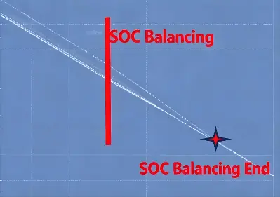
- Physical principle: SOC differences between battery clusters arise from differences in internal resistance and temperature. Traditional passive balancing simply dissipates the excess energy. The SST approach exploits the module-level bidirectional power capability: the EMS computes each cluster's SOC and actively transfers energy from high-SOC clusters to low-SOC ones.
- Quantified benefit: usable energy +6%, and longer battery life (overcharge/over-discharge avoided).
5.3 Highlight 3: N+X Module Redundancy
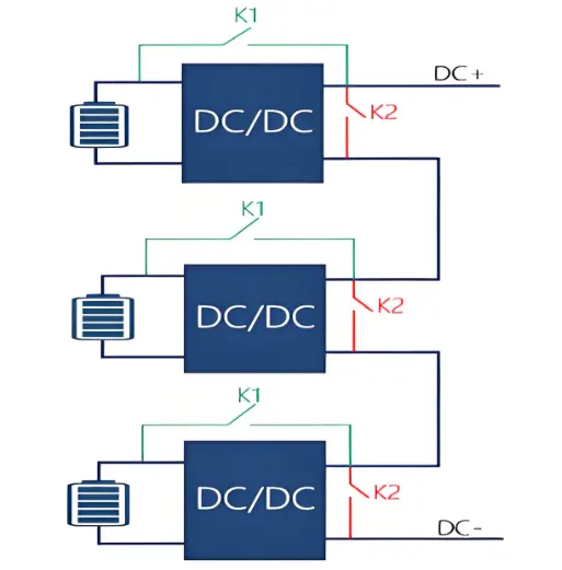
- Physical principle: the SST modules run in N+X hot standby. When any module fails, the EMS detects it and seamlessly bypasses the faulty module while the remaining modules automatically share the power.
- Quantified benefit: single-point-failure loss <0.1% (vs. 100% plant shutdown in a CHB cascade).
6. Economic Comparison with the Traditional Approach
6.1 25-Year Lifecycle TCO Comparison (100 MW / 200 MWh baseline)
| Cost item | Traditional (RMB 10k) | SST direct-connect (RMB 10k) | Saving |
|---|---|---|---|
| Initial investment | 3,200 | 2,900 | −9.4% |
| Transformer annual maintenance | 45 | 8 | −82% |
| No-load loss (25 years) | 1,350 | 0 | −100% |
| Battery replacement (SOC-balancing benefit) | 1,200 | 1,050 | −12.5% |
| 25-year TCO | 12,750 | 10,230 | −19.8% |
6.2 Payback Analysis
- Extra initial investment: ~RMB 1.5 million (SST equipment premium)
- Annual operating savings: ~RMB 1.8 million
- Payback period: ~10 months
7. Landmark Project References
| Project | Configuration | Key measured data | Significance |
|---|---|---|---|
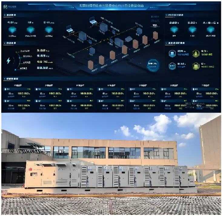
| GDS Chongqing | 1.2 MW / 2.4 MWh | 90% overall efficiency; 99% SOC balancing charge/discharge depth | Data-centre storage model |
| Guangdong Power Grid, 6-district interconnection | Multi-district flexible interconnection | 98.7% equipment efficiency (+4%) | Distribution-network flexible-interconnection model |
| CNPC Kunshan | SST ultra-fast hybrid charging station | 95%+ efficiency; −40% footprint | World-first installation |
8. Technical Standards and Compliance
| Category | Standard | Scope |
|---|---|---|
| Grid connection | GB/T 34120 | Technical regulations for electrochemical energy-storage systems connected to the grid |
| Battery safety | GB/T 36276 | Lithium-ion batteries for electric energy storage |
| Converter | GB/T 34133 | Technical specifications for energy-storage converters |
| Fire-fighting | GB/T 42288 | Safety regulations for electrochemical energy-storage power plants |
| International | IEC 62933 | Series of standards for electric energy-storage systems |
9. Delivery and Services
9.1 Delivery Model
| Phase | Duration | Scope |
|---|---|---|
| Solution design | 2 weeks | Site survey, capacity configuration, system design |
| Factory pre-fabrication | 6 weeks | Modular production, factory testing |
| On-site installation | 4 weeks | Lifting, wiring, commissioning |
| Grid-connection acceptance | 2 weeks | Full grid-connection tests, grid acceptance |
| Total | 14 weeks | 30% shorter than traditional |
9.2 Full-Lifecycle Services
- Warranty: battery 10 years / SST 5 years / system 3 years
- O&M: remote monitoring + annual inspection + 24-hour emergency response
- Upgrades: OTA remote upgrade of EMS software
Deployed Equipment
-
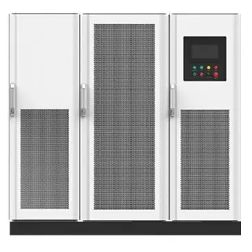 RWSST High Efficiency Solid State Transformer 8.5kV to 40.5kVRWSST Series 840–3360 kVA, featuring ultra-high efficiency, outstanding safety & reliability, flexible combination and prefabricated design.The single system adopts N+3 redundancy to form an N+X architecture, delivering higher reliability. It optimizes power supply structure, achieves higher efficiency, faster deployment and more flexible power distribution solutions.Built-in prefabricated structure, cabinets are connected via busbars, which greatly reduces installation costs such as c
 -
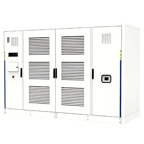 Modular Solid State Transformers for Adaptable Energy IntegrationProduct DescriptionSolid-state transformers (SSTs), also known as power electronic transformers, are based on the core concept of Power Electronic Building Blocks (PEBB). They generally employ a modular series-parallel topology to facilitate the flexible integration of varying voltage levels, capacity ratings, and forms of electrical energy, thereby enabling adaptable configurations for diverse application scenarios.FeaturesSmall size, few links, average efficiency improvement 3% (2%~5%)High fre
 -
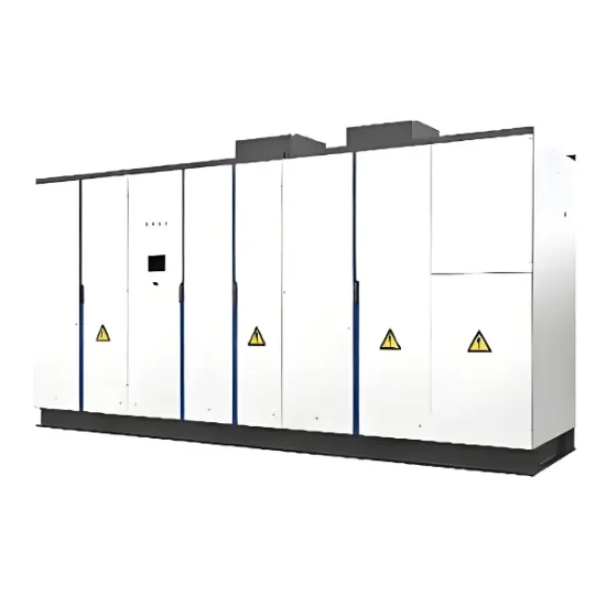 Modular Solid State Transformer for Data Centers based on PEBB TechnologyTheData Center Solid State Transformer (SST), also known as the Power Electronic Transformer (PET), represents the next generation of green power distribution for mission-critical facilities. Built on the core philosophy ofPower Electronic Building Blocks (PEBB), it utilizes an advanced modular series-parallel topology. Unlike traditional transformers, the SST enables millisecond-level voltage regulation and fault isolation. It serves as an "Energy Router," providing flexible access for various