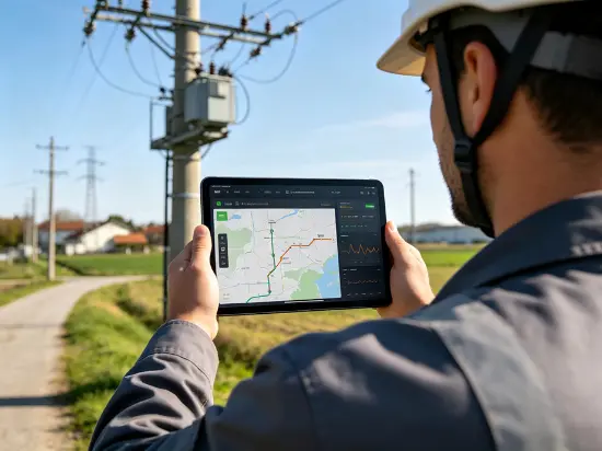
Distributed Fault Precise Localization System Solution for Transmission Lines
One-sentence conclusion
This solution deploys dual-mode distributed fault location terminals—both contact-based and non-contact-based—for transmission lines above 35 kV, with intervals ranging from 5 to 30 km. It achieves a fault location accuracy of ≤ ±100 m, a segment-level positioning reliability of ≥ 99%, and an identification accuracy for lightning-induced versus non-lightning-induced faults exceeding 95%. As a result, fault patrol time is reduced from hours to minutes.
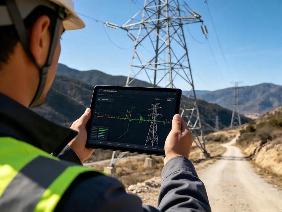
I. Industry Pain Points
- Transmission lines are long and span numerous sections; after a fault occurs, manual line inspections can take anywhere from several hours to several days, wasting valuable repair windows.
- Lightning strikes, external damage, and wildfires can trigger transient faults; traditional steady-state detection methods are unable to capture traveling-wave transient signals.
- The causes of lightning strikes, non-lightning strikes, bypass strikes, and back strikes are intertwined, making it difficult to match the appropriate mitigation strategies precisely.
II. Solution Architecture
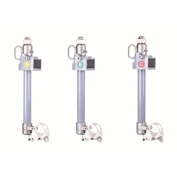
Distributed fault location terminal (installed on poles/towers and conductors) + master station system (fault analysis and location software + application/data server) + mobile handheld terminal. It supports both contact-based (traveling-wave current measurement) and non-contact (electric field voltage measurement) modes, allowing for mixed deployment within the same network and flexible blind-spot coverage.
- Contact-type: Traveling-wave sensor bandwidth 1 kHz to 2 MHz, single-wire fault current range 10 A to 5000 A, traveling-wave recording duration 500 μs;
- Non-contact: Traveling-wave voltage frequency response: 30 Hz to 1 MHz; sampling rate > 1 MHz; continuous recording duration > 1000 μs; voltage linearity: 10 V to 10,000 V (±10% ± 10 V, reference electric field: 10,000 V/m).
- The terminals are all installed in a non-series bypass configuration, and single-point failures do not affect the operation of the primary equipment or the main circuit.
III. Core Technical Indicators
|
Indicator |
Contact-based |
Non-contact |
|
Applicable Voltage |
35kV and above |
35kV and above |
|
Positioning error |
≤±100m |
≤±100m |
|
Interval positioning reliability |
≥99% |
≥99% |
|
Lightning strike identification accuracy |
>95% (lightning/non-lightning, side flash/counterstrike) |
>95% (lightning/non-lightning, side flash/counterstrike) |
|
Time reference |
BDS ≤ 0.03 μs |
BDS ≤ 0.03 μs |
|
Traveling-wave bandwidth/sampling |
1kHz~2MHz |
Voltage: 30 Hz to 1 MHz; Sampling rate > 1 MHz |
|
Fault Range |
Current: 10A ~ 5000A |
Voltage: 10V~10,000V |
|
Recording duration |
500microseconds |
>1000 μs |
|
Protection/Material |
IP67 / Aluminum die-cast <6kg |
Pole and tower installation—waterproof, moisture-proof, and corrosion-resistant. |
|
Environmental adaptation |
-40~+70℃; altitude ≤5000m; gusts ≤45m/s; GB 50545 heavy ice zone |
-40~+70℃; altitude ≤5000m; gusts ≤45m/s; GB 50545 heavy ice zone |
IV. Deployment Recommendations
- Deployment: The spacing between adjacent monitoring points should be 5–30 km. Monitoring points must be installed at transmission-line towers on the power supply side, and the density of monitoring points should be increased along the middle sections of long transmission lines.
- Form selection: In areas with frequent lightning strikes, prioritize contact-based sensors (with current ranges covering lightning currents); in sections with restricted access, supplement with non-contact sensors to fill coverage gaps.
- Communication Security: Communication with the master station supports VPN/encryption and is configured in accordance with power secondary security requirements.
- Acceptance: The positioning error shall be verified by actual line testing (non-contact traveling-wave voltage measurement segment error ±10%).).
V. Application Value
|
Operations and Maintenance Phase |
Traditional model |
After deploying this solution |
|
Fault Detection |
Manual Inspection/Steady-State Detection |
Traveling-wave transient detection, 24-hour online |
|
Fault Localization |
Line patrol segment by segment, from hourly to daily levels. |
≤±100m, minute-level locking |
|
Cause Determination |
On-site experience |
Lightning strike vs. non-lightning strike >95% identification |
|
Data Management |
Decentralized record |
Centralized traceability, VPN encryption |
Reference Projects
-
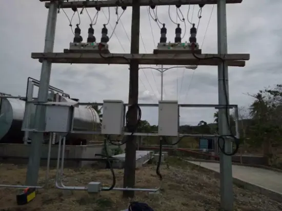 RW Energy Bangladesh 230 Units 11 kV Vacuum Circuit Breaker Intelligence Retrofit Case StudyFocusing on Bangladesh’s distribution network automation upgrade demands, the intelligent retrofitting of 230 sets of 11kV VCBs integrates intelligent control and anti-corrosion technologies. Adopting a cost-effective renewal model for legacy grids, it enables equipment reuse and efficiency improvement, advances regional distribution network digital transformation, and sets a benchmark for the intelligent upgrading of aging switchgear in South Asia.01 Project Overview1.1 Project BackgroundIn De
 -
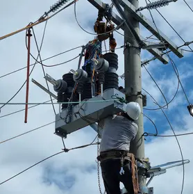 RW Energy Tanzania 325 Units 33 kV Auto Recloser Project Case StudyFocusing on the medium‑voltage distribution network upgrading demands in Tanzania, this solution adopts 325 sets of high‑reliability 33kV auto-reclosers integrated with FTU intelligent control and high environmental adaptability technologies to isolate faults and restore power supply rapidly, consolidating the stable foundation of regional power grids.01 Project Overview1.1 Project BackgroundIn 2025, 325 units of 33 kV auto reclosers were officially supplied and applied to the Tanzania medium-v
 -
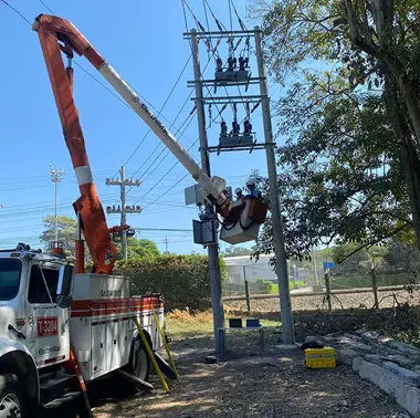 RW Energy Colombia PV Plant 35 kV Recloser Controller Project Case StudyFacing the frequency fluctuation and grid connection challenges of Colombia’s low-inertia photovoltaic power grid, this solution leverages customized recloser control and optimized frequency protection technologies to precisely adapt to the local 60Hz grid standard. It effectively addresses grid fluctuation issues under complex grid connection conditions, delivering a highly reliable and strong anti-interference grid protection solution for photovoltaic power plants and ensuring their stable an
 -
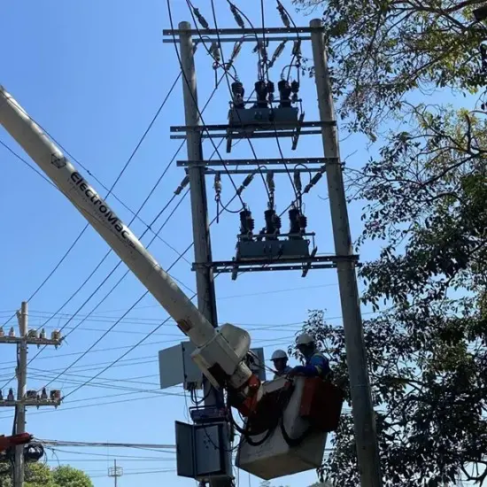 420 Units of 11 kV Automatic Reclosers for Dhaka Grid Upgrade01 General Overview: Dhaka 11 kV Distribution Grid Upgrade1.1 Project BackgroundBangladesh is currently undergoing a period of rapid economic and industrial development, and the growing demand for electricity has placed immense pressure on the local distribution networks. However, the country's existing 11 kV backbone distribution lines are facing severe equipment aging issues. The original switchgear suffers from serious mechanical wear, resulting in not only high failure rates but also sluggi
 -
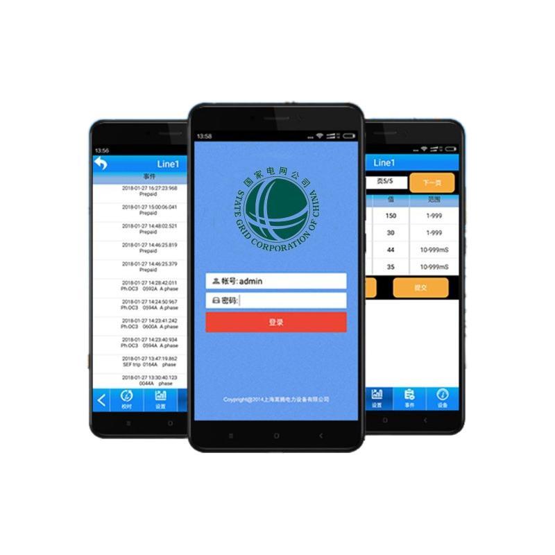 RW Energy Multi Country SMS Based Auto Recloser Controller Case StudyBreaking the communication bottlenecks in remote areas worldwide, this solution takes SMS communication as its core innovation and develops recloser controllers adaptable to multiple countries and diverse climates. Free from reliance on 4G networks, it enables rapid fault early warning and remote operation & maintenance management, helping various regions resolve distribution network operation challenges in remote areas and inject intelligent momentum into global rural power grid upgrading.0
 -
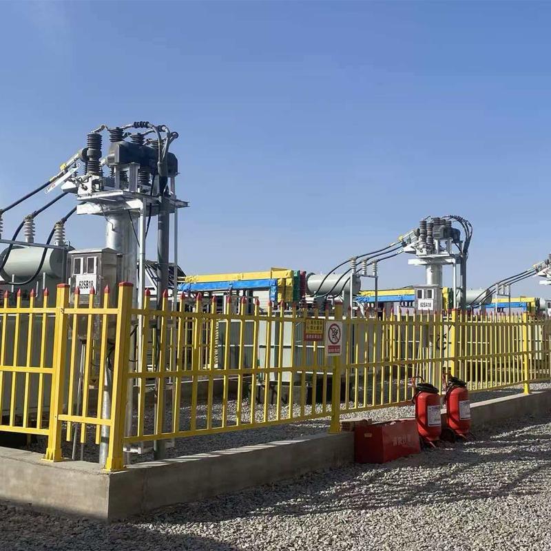 RW Energy Xinjiang Bazhou Large-scale Data Center 6 kV Industrial Grid Intelligent Power Distribution Upgrade Case StudyFocusing on the high-reliability power supply demands of data centers, this project upgrades the 6kV industrial intelligent power distribution system. It enhances anti-sandstorm and wide-temperature environmental adaptability, integrates rapid protection and remote intelligent operation and maintenance technologies, stably supports high-density computing loads, and empowers the intelligent transformation of power grids in western computing hubs.01 Project Overview1.1Project BackgroundBayingolin
 -
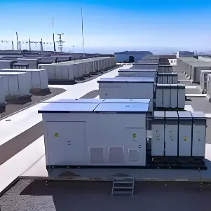 Angola Dadi Energy Storage 35 kV Power Quality Improvement success storyThe Angola Dadi Energy Storage power quality improvement project is a 35 kV power quality retrofit implemented on an existing energy storage plant. On-site nonlinear, high-harmonic loads such as inverters — power conversion systems (PCS) — are densely concentrated, a typical harmonic-source-intensive scenario in which harmonic pollution seriously hampers production efficiency and product quality.An H5+H7 filter compensation bank with a total capacity of 7500 kvar was provided to deliver harmonic