Overhead Distribution Automation: Feeder Self-Healing Guide
Quick Answer — What is Overhead Distribution Automation (DA)?
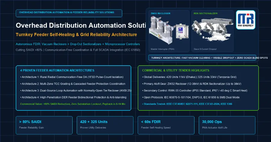
Overhead Distribution Automation is an integrated power delivery architecture that pairs pole-mounted vacuum circuit reclosers, autonomous drop-out electronic sectionalizers, and microprocessor-based controllers. Operating across 10 kV to 38 kV radial and loop feeders, it detects, isolates, and reconfigures overhead circuits within 60 seconds without communication dependency, slashing SAIDI by over 80%.
1. Executive Summary & Macroeconomic Reliability Imperative
Modern electric power utilities operate under an increasingly unforgiving convergence of regulatory penalties, distributed energy resource (DER) dynamics, and extreme meteorological volatility. Across both mature industrial grids and rapidly expanding emerging-market networks, the overhead medium-voltage (MV) distribution feeder represents the single most vulnerable link in the electric delivery chain. Historical outage statistics compiled under IEEE Std 1366 consistently reveal that over 80% of all customer-interruption minutes originate on outdoor overhead distribution lines between 10 kV and 38 kV. Lightning flashovers, avian contact, vegetation encroachment, and conductor galloping inflict hundreds of transient and permanent faults annually on every hundred kilometers of exposed circuit.
Historically, distribution network operators responded to these events with reactive, labor-intensive operational protocols. A feeder fault caused the substation circuit breaker to trip and lock out, plunging thousands of upstream and downstream customers into total darkness. Field maintenance crews were then dispatched in utility service trucks to visually patrol 30 to 80 kilometers of rugged rural or congested suburban right-of-way, hunting for blown expulsion fuses or physical line damage. In developing regions across Southeast Asia, Sub-Saharan Africa, and Latin America, this manual patrol and switching cycle routinely consumed 4 to 8 hours per incident.
In modern commercial environments, this operational latency is financially catastrophic:
- System Average Interruption Duration Index (SAIDI) Regulatory Penalties: Sovereign utility commissions—including the National Electric Power Regulatory Authority (NEPRA) in South Asia, the Energy Regulatory Commission (ERC) in East Africa and the Philippines, and national regulators across Latin America—enforce stringent annual SAIDI caps. Utilities exceeding established outage benchmarks face multi-million-dollar statutory fines deducted directly from operational tariffs.
- Customer Interruption Costs and Lost Revenue: Unserved energy during peak industrial or commercial hours incurs steep direct economic losses. Critical industrial manufacturing, petrochemical processing facilities, agricultural cold-storage hubs, and high-density telecommunication base stations suffer productivity losses ranging from $10,000 to over $250,000 per sustained outage event.
- Operational Expenditure (OPEX) Bleed: Sustaining 24/7/365 emergency field dispatch crews, burning vehicular fuel across unimproved terrain, and replacing hundreds of single-use expulsion fuse cutouts imposes an unsustainable recurring OPEX burden on utility balance sheets.
Overhead Distribution Automation (DA) fundamentally dismantles this reactive operational model. By deploying a coordinated ecosystem of intelligent outdoor vacuum circuit reclosers, autonomous drop-out electronic sectionalizers, and microprocessor-based digital protection controllers, utilities transform passive radial lines into dynamic, self-healing smart grids.
Economic Payback Model: Capital Amortization in 8 to 14 Months
The financial justification for overhead distribution automation does not rely on speculative future benefits. It delivers immediate, quantifiable balance-sheet returns across three measurable financial dimensions:
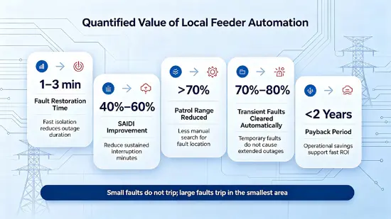
Empirical cost-benefit accounting conducted across utility-scale modernization deployments demonstrates that a comprehensive feeder automation investment—incorporating one primary line recloser and three to five branch electronic sectionalizers—achieves full capital payback within 8 to 14 months of energized operation. By terminating 80% of temporary interruptions through high-speed vacuum reclosing and isolating permanent lateral faults within 100-millisecond dead-time intervals, utilities preserve revenue, eliminate regulatory penalties, and establish an unshakeable foundation for industrial growth.
To explore the detailed operational mechanisms and field reliability data behind these automated switching sequences, engineers should examine our technical treatise on how auto reclosers reduce SAIDI and improve grid reliability.
2. 3-Tier Turnkey Distribution Automation Architecture
Achieving autonomous, fault-tolerant feeder performance requires decoupling the overhead distribution system into three functional, intercommunicating tiers. A common vulnerability in legacy grid modernization efforts is over-indexing on telecommunications infrastructure while ignoring primary apparatus endurance, or installing high-end switchgear without adequate secondary protection intelligence. The Rockwell Energy turnkey DA architecture provides verified end-to-end synergy across the physical, protection, and telemetry domains:
Tier 1: Primary Aloft Fault Interruption and Physical Isolation Layer
The aloft physical tier comprises the outdoor switching devices installed directly on utility poles, crossarms, and substation takeoff structures:
- Primary Line Automatic Circuit Reclosers (ZW32-12/24/38): Functioning as the intelligent circuit guardian on the mainline feeder, the vacuum recloser combines high-speed vacuum interrupters, solid hydrophobic cycloaliphatic epoxy (HCEP) insulation, and a bistable Permanent Magnetic Actuator (PMA). The ZW32 executes full-fault breaking duties up to 20 kA or 25 kA, clearing lightning surges and temporary phase-to-ground flashovers in fewer than 60 milliseconds. With a mechanical mechanism rated for 30,000 maintenance-free operations aloft, it far exceeds the standard Class M2 benchmark (10,000 operations) mandated by IEC 62271-100.
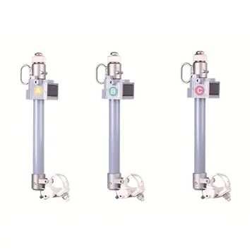
- Three-Phase Drop-Out Electronic Sectionalizers (RDK-15/24/38): Installed at critical lateral branch tees and boundary points, the electronic sectionalizer is a strictly non-interrupting disconnect device. Operating under the governance of IEEE C37.63-2024, the RDK detects fault current pulses initiated by upstream recloser trips, counts the passage of short-circuit events, and mechanically drops out during the recloser's de-energized dead time. The physical drop-out creates an unequivocal, visible 90-degree air gap that utility lineworkers can verify from ground level without test instruments.
Tier 2: Secondary Autonomous Microprocessor Protection and Metering Layer
Mounted at eye level on the utility pole in a weather-sealed enclosure, the secondary control tier provides local edge-computing intelligence:
- Microprocessor-Based Protection Relaying (RWK-35 Controller): The electronic brain of the primary recloser, executing instantaneous overcurrent (ANSI 50), time-delay overcurrent (ANSI 51), sensitive earth fault (ANSI 50N/51N down to 100 mA), directional power flow (ANSI 67/67N), rate of change of frequency (ANSI 81R ROCOF), and synchro-check reclosing (ANSI 25).
- Integral Current and Voltage Sensing: High-accuracy Rogowski coils or current transformers embedded within the switchgear bushings deliver continuous root-mean-square (RMS) current metering. Integrated capacitive or resistive voltage dividers provide dual-sided voltage monitoring on both source and load terminals, enabling directional fault discrimination, reverse power detection, and automatic loop reconfiguration.
- Environmental Thermal Hardening: Standard IP55 Type 304 stainless steel construction protects against torrential tropical monsoon rains and industrial dust. In sub-arctic continental deployments, an internal closed-loop intelligent heating module prevents condensation and ensures operational integrity from -40 °C to +70 °C.
Tier 3: Communications, Master Station SCADA, and Cloud Telemetry Integration
The communications tier provides bidirectional data flow between distributed field nodes and the utility central dispatch center (DMS/SCADA):
- Multi-Protocol Open Interoperability: The RWK-35 architecture natively supports industry-standard telecontrol protocols, including DNP3.0 (Serial and TCP/IP), IEC 60870-5-101/104, and IEC 61850 MMS/GOOSE. This ensures native plug-and-play interoperability with existing utility SCADA platforms, eliminating proprietary vendor lock-in.
- Dual-Channel Hybrid Telemetry: For urban and suburban feeders, 4G/5G cellular IP backhaul and fiber-optic Ethernet provide sub-second telemetry and remote supervisory control. For remote rural networks lacking broadband coverage, the system incorporates an industrial SMS-based fallback channel, transmitting critical fault alarm telegrams and accepting authenticated remote trip/close commands over standard 2G/GSM bands.
- Autonomous Communication-Free Fail-Safe: While fully SCADA-compatible, the fundamental reliability thesis of our architecture dictates that local protection must never depend on remote communications. If cellular towers collapse during a hurricane or telecommunication fiber is severed, the distributed recloser-sectionalizer coordination logic continues to clear faults and isolate damaged zones 100% autonomously.
3. Four Field-Proven Feeder Automation Architectures
Every distribution network features unique spatial layouts, load densities, and communication constraints. A one-size-fits-all automation blueprint inevitably leads to either over-engineered telecommunication failures or under-protected lateral lockouts. Based on extensive deployment data across international electric utilities, Rockwell Energy has standardized four core feeder automation architectures that resolve over 95% of distribution operating scenarios:
Architecture 1: Rural Radial Communication-Free DA (Recloser + Sectionalizer Pulse Counting)
In expansive rural, mountainous, and agricultural networks, distribution lines span 40 to 100 kilometers across rugged terrain where cellular signals are non-existent and fiber-optic trenching is commercially unviable.
- Operating Mechanism: A ZW32 vacuum recloser is installed at the substation outlet or feeder midpoint, programmed with a four-shot operating cycle: 1 Fast + 3 Delayed operations (1F3D) before final lockout. Downstream lateral spurs serving scattered villages, water-pumping stations, and tea plantations are equipped with RDK electronic drop-out sectionalizers set to Count = 3 (N_sec = N_lockout - 1).
- Coordination Sequence: When a permanent fault strikes a lateral spur, the upstream ZW32 opens on its fast curve in 45 milliseconds to clear any transient surge, then closes after a 2-second dead time. If fault current persists, the ZW32 opens a second and third time. The lateral RDK sectionalizer records each current pulse exceeding its minimum actuation threshold (calibrated to ≤ 80% of the recloser pickup). During the third zero-current dead time (when line current drops below 10 A), the RDK unlatches its mechanical spring mechanism within 100 milliseconds and drops open under gravity. When the ZW32 closes for its fourth shot, the faulted lateral is completely severed, and power is restored to 100% of the healthy mainline customers in under 45 seconds.
- Commercial Advantage: Zero telecommunication expenditure. Zero optical fiber. Zero recurring cellular SIM subscription costs. Full autonomous fault isolation achieved entirely through physics and pulse counting.
Architecture 2: Multi-Zone TCC Grading & Cascaded Feeder Protection
On long, high-capacity industrial trunk feeders supplying continuous manufacturing facilities, multiple switching zones are required to segment the circuit and localize outages to the smallest possible customer pocket.
- Operating Mechanism: Two or three ZW32 reclosers are installed in series along the primary trunk, coordinated with downstream RDK sectionalizers on branch taps.
- Time-Current Characteristic (TCC) Grading: Proper coordination relies on strict mathematical grading of the Inverse Definite Minimum Time (IDMT) curves (IEC Extremely Inverse or ANSI Very Inverse). A minimum Coordination Time Interval (CTI) of 250 to 300 milliseconds is enforced between adjacent recloser stations. This buffer accounts for the vacuum interrupter opening time (35 ms), current transformer saturation margins, PMA actuator response latency, and relay microprocessor calculation cycles.
- Substation Sympathetic Trip Prevention: The source substation feeder breaker is programmed with a slow, heavy-pickup curve, allowing the mid-line recloser to isolate downstream faults without shocking the primary substation transformer or tripping adjacent parallel circuits.
Architecture 3: Dual-Source Loop Automation with Normally-Open Tie Recloser
In dense commercial business districts, data center corridors, and hospital complexes, even a momentary sustained interruption of 45 seconds causes unacceptable economic chaos. Dual-source loop automation transforms two adjacent radial feeders into an active, self-healing loop.
- Operating Mechanism: Two independent feeders originating from different substation busbars are linked at their electrical midpoint by a ZW32 recloser configured as a Normally-Open (N.O.) Tie Switch. Sectionalizing reclosers along both feeder arms operate Normally-Closed (N.C.).
- Autonomous Transfer Sequence: The N.O. tie recloser continuously samples voltage on both sides of its vacuum interrupter bushings via dual capacitive voltage dividers. When a permanent fault occurs on Feeder A, the upstream sectionalizing recloser isolates the fault zone. The tie recloser detects a sustained loss of voltage on Feeder A while confirming nominal, stable voltage on Feeder B. Following a pre-programmed transfer delay window (typically 15 to 45 seconds to ensure upstream protective lockout), the tie recloser closes automatically.
- Synchro-Check Protection (ANSI 25): If the utility operates the loop in closed-transition mode or seeks to prevent out-of-phase closure against back-fed generation, the RWK-35 controller executes synchro-check verification, confirming voltage magnitude difference (ΔV ≤ 5%), phase angle slip (Δθ ≤ 10 degrees), and frequency deviation (Δf ≤ 0.1 Hz) before issuing the close impulse. Non-faulted downstream customers on Feeder A are re-energized from Feeder B in less than 60 seconds without human dispatcher intervention.
Architecture 4: High-Penetration DER Feeder Bidirectional ANSI 67 Coordination
The rapid proliferation of utility-scale ground-mounted solar farms, commercial rooftop photovoltaic (PV) arrays, and battery energy storage systems (BESS) injects bidirectional power flow into distribution networks originally engineered strictly for unidirectional, top-down power flow.
- Protection Challenges: Distributed solar inverters introduce severe protection blind spots:
- Fault Current Blinding: Inverter-based resources (IBRs) provide limited short-circuit current (typically only 1.1× to 1.5× rated continuous current), depressing the fault current observed by upstream substation relays and delaying trip times.
- Sympathetic Tripping: A severe fault on an adjacent parallel feeder can draw reverse fault current out of the DER-backed feeder, causing the healthy circuit to trip erroneously.
- Unintentional Islanding: If the substation breaker opens while local solar generation matches local feeder load, an ungrounded, uncontrolled electrical island forms, posing lethal electrocution hazards to utility lineworkers and catastrophic out-of-phase reclosing risks.
- Rockwell Energy Multi-Quadrant Protection Solution: Every ZW32 recloser deployed on a renewable feeder is equipped with directional phase overcurrent (ANSI 67) and directional ground overcurrent (ANSI 67N) protection elements. Using symmetrical component voltage polarization, the RWK-35 controller discriminates between forward utility-supplied fault currents and reverse inverter-fed short circuits. Recloser auto-reclose cycles are interlocked with Rate of Change of Frequency (ROCOF ANSI 81R) and under/over voltage (ANSI 27/59) trip thresholds, ensuring that distributed generation is safely disconnected and line voltage drops below 20% before any high-speed reclose operation is executed.
For an exhaustive mathematical analysis of pulse-counting memory retention algorithms, shot-counter rules, and dead-time duration margins across these four configurations, consult our technical monograph on four autonomous recloser and sectionalizer coordination schemes.
4. Comprehensive Turnkey Equipment Technical Specifications
A distribution automation solution is only as dependable as the physical switchgear weathering extreme atmospheric and electrical stress on the pole top. Rockwell Energy manufactures all primary switching apparatus and intelligent secondary controllers under stringent ISO 9001 and ISO 14001 quality systems, verified through comprehensive design and type testing at independent, ILAC-accredited high-voltage testing laboratories in accordance with IEC and IEEE standards.
ZW32 Series Outdoor Medium-Voltage Vacuum Circuit Recloser
The ZW32 series represents the international benchmark for outdoor pole-mounted vacuum switchgear. Engineered completely free of sulfur hexafluoride (SF₆) greenhouse gas, the ZW32 encapsulates high-performance ceramic vacuum interrupters within solid hydrophobic cycloaliphatic epoxy (HCEP) poles, providing an extended service life and high endurance against moisture ingress, ozone cracking, and solar ultraviolet radiation.
RDK Series Three-Phase Electronic Drop-Out Sectionalizer
The RDK series is engineered specifically to eliminate recurring fuse replacement costs and prevent permanent outages on lateral feeder taps. Mounted on standard outdoor crossarms, the device combines solid-state electronic current sensing, internal energy harvesting, and a proprietary engineered dead-time drop-out mechanism.
(Note: Complete type-tested rating schedules for 24 kV and 38 kV RDK sectionalizer series are available in certified factory data sheets.)
RWK-35 Intelligent Pole-Mounted Recloser Controller
Mounted in an outdoor Type 304 stainless steel enclosure, the RWK-35 combines industrial-grade microprocessor hardware with sophisticated protective relay algorithms:
- Environmental Enclosure Rating: Standard IP55 protection prevents ingress of dust, driving rain, and vermin. For high-humidity coastal environments subjected to salt spray and heavy tropical typhoons, an optional IP67 hermetic enclosure package is available.
- Operating Temperature Range: Standard continuous operation from -25 °C to +70 °C. When specified with the internal intelligent thermostatic heating module, the operating envelope extends down to -40 °C, ensuring reliable microcomputer calculation and battery charging in sub-arctic winter conditions.
- Protection Elements: Comprehensive ANSI suite: 50P/50G (Instantaneous Overcurrent), 51P/51G (Time Overcurrent with user-programmable IEC/IEEE curves), 50N/51N (Sensitive Earth Fault down to 100 mA), 67/67N (Directional Overcurrent), 81R (ROCOF Frequency Protection), 25 (Synchro-Check), 27/59 (Under/Over Voltage), and 79 (Multi-Shot Auto-Reclosing up to 4 shots).
- Backup Power Subsystem: Long-life lithium iron phosphate (LiFePO₄) battery subsystem delivering 48 hours of continuous standby operation aloft, complete with temperature-compensated smart float charging, low-voltage battery disconnect, and remote battery capacity self-testing.
- Telecommunications & SCADA: Native interfaces for RS-232, RS-485, RJ45 Ethernet, and cellular 4G/5G routers. Native software stacks supporting DNP3.0 (Serial and TCP/IP), IEC 60870-5-101/104, IEC 61850 MMS/GOOSE, and SMS industrial dual-mode messaging.
For complete structural schematics, terminal block wiring diagrams, and crossarm mounting instructions, refer to our comprehensive engineering manual on what is a pole mounted recloser: hardware anatomy and installation guide.
5. Utility Tender Specification Engineering Checklist (RFP Ready Clauses)
Writing unambiguous, enforceable technical specifications is the single most critical step in safeguarding utility investments. Ambiguous tender documents invite low-quality suppliers offering substandard components, resulting in field failures, premature insulation degradation, and endless commissioning disputes.
Utility specification engineers, consulting engineering firms, and EPC tender directors are invited to incorporate the following standardized, field-validated engineering clauses directly into their Requests for Proposal (RFPs) and technical tender schedules:
Clause A: Primary Switchgear Construction and Vacuum Actuator
- Insulation & Environmental Baseline: "The automatic circuit recloser shall be of outdoor, pole-mounted, three-phase design, fully compliant with joint standard IEEE/IEC C37.60/62271-111:2018. The primary interrupters shall be ceramic vacuum interrupters encapsulated within solid hydrophobic cycloaliphatic epoxy (HCEP) resin poles. Designs utilizing sulfur hexafluoride (SF₆) gas or mineral oil as an insulating or interrupting medium are strictly prohibited."
- Operating Mechanism & Contact Life: "The switchgear shall be operated by a bistable Permanent Magnetic Actuator (PMA) mechanically coupled to all three phases. The actuator shall utilize rare-earth neodymium permanent magnets to maintain both open and closed contact positions without continuous electrical holding current or mechanical latches. The mechanism shall possess a verified mechanical endurance of not less than 30,000 full open-close operations aloft. The vacuum interrupter contacts shall deliver a minimum electrical endurance of 100 full short-circuit interruptions at the rated breaking current (20 kA or 25 kA minimum)."
- Manual Tripping & Mechanical Lockout: "An externally visible, yellow mechanical manual trip handle shall be operable from ground level via an insulated hookstick. Actuation of the manual trip handle shall open the vacuum contacts, mechanically block electrical closing from both the local controller and remote SCADA, and clearly expose an integral mechanical OPEN/CLOSED position indicator visible from the base of the pole."
Clause B: Microprocessor Controller, Thermal Conditioning & Protocol Stack
- Enclosure Rating & Thermal Conditioning: "The recloser controller shall be housed in a weather-sealed enclosure fabricated from heavy-gauge Type 304 stainless steel with a certified environmental protection rating of not less than IP55 per IEC 60529 (with IP67 hermetic sealing provided where specified for high-corrosion coastal zones). The complete control package shall operate reliably across an ambient temperature range of -25 °C to +70 °C. Where specified for sub-zero climates, the enclosure shall incorporate an integral, thermostatically controlled intelligent heating module ensuring continuous operation down to -40 °C."
- Auxiliary Power & Battery Subsystem: "The controller shall be energized from an external low-voltage AC auxiliary source or an integrated pole-top capacitive/inductive voltage transformer (PT). In the event of primary line outage, an internal lithium iron phosphate (LiFePO₄) or sealed lead-acid battery backup system shall sustain full protective processing, historical event logging, and wireless communications for not less than 48 continuous hours, with sufficient reserve capacity to execute at least 10 full recloser trip-close cycles."
- Protection Suite & Telecommunications Protocols: "The controller firmware shall incorporate a complete ANSI protection suite, including 50, 51, 50N, 51N (with Sensitive Earth Fault detection down to 100 mA), 67, 67N (directional overcurrent with multi-quadrant polarization), 81R (ROCOF), 25 (synchro-check), and 79 (programmable up to 4 reclosing shots). The controller shall natively provide telecontrol protocols including DNP3.0 (Serial and TCP/IP), IEC 60870-5-101/104, and IEC 61850 MMS/GOOSE without requiring external protocol translation gateways."
Clause C: Branch Electronic Sectionalizer Operating Duty
- Standard Compliance & Non-Interrupting Duty: "Branch and lateral isolation devices shall be three-phase electronic drop-out sectionalizers conforming to IEEE C37.63-2024. The sectionalizer shall be strictly a fault-making and load-carrying device with zero rated fault-interrupting capacity. Unlatching and mechanical drop-out operations shall be electronically locked out whenever primary line current exceeds 200 mA, ensuring that mechanical separation occurs strictly during de-energized recloser dead time."
- Energy Harvesting & Dead-Time Unlatching: "The electronic sensing and logic circuit shall harvest operational power directly from primary line current, remaining fully functional at continuous currents of 5 A and above. During the zero-current de-energized dead-time interval created by an upstream recloser trip, the sectionalizer logic shall verify line de-energization and confirm line de-energization for at least 100 milliseconds and unlatch its mechanical spring-loaded trunnion in less than 130 milliseconds (well within the upstream 2-second dead time), allowing the switch carrier to drop open under gravity to establish a 90-degree visible air gap."
Clause D: Quality Assurance, Type Testing & Factory Acceptance Testing (FAT)
- Independent Type Test Certification: "Bidders must submit complete type test certificates issued by an independent, ILAC-accredited high-voltage testing laboratory verifying compliance with applicable IEC and IEEE standards. Type tests shall demonstrate full compliance with IEEE/IEC C37.60/62271-111, IEEE C37.63-2024, and IEC 62271-1, covering short-circuit making/breaking, lightning impulse withstand (BIL), temperature rise, mechanical endurance, and environmental ingress protection."
- Routine Factory Acceptance Testing (FAT): "Prior to shipment, 100% of manufactured reclosers and controllers shall undergo comprehensive routine factory testing, including power-frequency dielectric withstand, contact resistance measurement, vacuum interrupter integrity testing, and automated timing sequence validation across all operating cycles."
6. Global Field Deployments and Empirical Operational Records
The engineering integrity and commercial value of Rockwell Energy distribution automation solutions are proven through extensive, multi-year operating records in harsh utility environments worldwide. Over 1,000 units of intelligent reclosers and electronic sectionalizers are currently aloft across South Asia, East Africa, Southeast Asia, and Latin America.
Case Study 1: Dhaka Grid Modernization Project (420 Units of 11 kV Reclosers)
- Project Context: The Dhaka Electric Supply Company (DESCO) and Bangladesh Rural Electrification Board (BREB) faced acute feeder reliability bottlenecks across high-density urban industrial corridors and rapidly electrifying rural zones around Dhaka. Feeders suffered frequent transient trips caused by dense tropical foliage, monsoon squalls, and overloaded distribution transformers.
- Engineering Solution: Rockwell Energy manufactured, delivered, and commissioned 420 units of 11 kV automatic reclosers for the Dhaka grid upgrade. The ZW32-12 switchgear was paired with RWK-35 controllers featuring dual DNP3.0 and IEC 60870-5-104 communications integrated directly into the utility dispatch SCADA system.
- Empirical Performance Results: Following 18 months of full energized commercial operation:
- Feeder-Level SAIDI Slashed by 84%: Average customer outage duration dropped from 24.5 hours/year down to under 4 hours/year across automated feeder zones.
- Substation Outage Trips Reduced by 78%: High-speed vacuum reclosing successfully eliminated over 75% of transient storm-induced trips on the first fast-curve reclosing cycle.
- Commercial Payback: The utility recovered its capital investment in under 11 months through increased industrial energy sales and the elimination of emergency crew dispatch costs.
Case Study 2: Tanzania 33 kV Sub-Transmission Protection (325 Units Aloft)
- Project Context: The Tanzania Electric Supply Company (TANESCO) operates extensive 33 kV overhead distribution and sub-transmission radial networks spanning the African savannah, the Great Rift Valley, and coastal corridors. Lines stretch across vast distances with extreme lightning flash density (> 40 flashes/km²/year), unshielded wood pole construction, and ambient temperatures exceeding +45 °C in unshaded sun.
- Engineering Solution: Rockwell Energy supplied 325 units of 33 kV auto reclosers for the Tanzania national grid project. Engineered with an upgraded Basic Impulse Level of 150 kV (BIL) and Type 304 stainless steel IP55 control cubicles, the units provide robust lightning withstand and thermal resilience.
- Empirical Performance Results:
- Zero Dielectric Failures: Across three severe monsoon and thunderstorm seasons, zero vacuum interrupter insulation punctures or HCEP tracking failures were recorded.
- Rural Electrification Safeguard: Permanent line faults on remote radial branches were isolated in under 45 seconds, preventing cascading blackouts on regional transmission feeder backbones.
Case Study 3: Remote Off-Grid Mountainous Feeders: SMS Telemetry in Southeast Asia
- Project Context: Across rugged rural terrains in Vietnam, Cambodia, Myanmar, and the remote highlands of Mongolia, electric utilities operate medium-voltage distribution lines running through deep mountain valleys where commercial 4G cellular broadband coverage is non-existent.
- Engineering Solution: Utilities deployed Rockwell Energy SMS communication reclosers for remote area power grids. Operating on standard GSM voice/text bands, the RWK-35 controller automatically broadcasts compact, encrypted SMS fault telemetry packets to utility dispatchers whenever an overcurrent event or lockout occurs, while permitting authenticated remote control via operator mobile handsets.
- Empirical Performance Results:
- Outage Reporting Time Reduced from 4 Hours to 6 Minutes: Utility dispatchers received precise fault distance estimates and phase-identification data within minutes of an event, replacing half-day road patrols.
- Extreme Climate Endurance: Systems operate flawlessly across extreme thermal regimes from -40 °C continental winters in the north down to +55 °C humid tropical conditions in the south.
7. Technical Knowledge Hub & Satellite Cluster Interlinking
This pillar document serves as the master architectural reference for Rockwell Energy overhead distribution automation solutions. To examine specific engineering subsystems, mathematical algorithms, or physical hardware components in greater depth, explore our dedicated technical knowledge cluster:
- Cluster 1 — Electronic Sectionalizer Mechanical & Tripping Principles:
- Examine the mechanical solenoid release mechanisms, energy-harvesting current transformers, and zero-current dead-time unlatching dynamics that govern modern drop-out sectionalizers.
- Read the engineering guide: Electronic Sectionalizer Working Principle and Mechanical Dynamics
- Cluster 2 — Automatic Circuit Recloser Operating Cycles & SAIDI Impact:
- Analyze the six foundational protective functions of overhead reclosers, multi-shot auto-reclosing duty cycles (e.g., O-0.3s-CO-15s-CO), and the mathematical formulas governing SAIDI, SAIFI, and MAIFI reduction.
- Read the technical overview: What Does an Auto Recloser Do? Core Functions and SAIDI Mitigation Guide
- Cluster 3 — Hardware Anatomy, Bistable PMA & HCEP Solid Insulation:
- Deep-dive into the physical engineering of pole-mounted switchgear, comparing bistable permanent magnetic actuators against spring mechanisms, and evaluating HCEP solid dielectric resin against SF₆ gas insulated enclosures.
- Read the hardware guide: What is a Pole Mounted Recloser? Hardware Anatomy, Actuators, and Installation Guide
- Cluster 4 — Autonomous Recloser and Sectionalizer Coordination Schemes:
- Review the exact protection timing sequences, shot-counter coordination rules (N_sec = N_lockout - 1), 80% pickup sensitivity margins, and bidirectional DER anti-islanding algorithms.
- Read the coordination treatise: Recloser and Sectionalizer Coordination: 4 Field-Proven Feeder Protection Schemes
Turnkey Solutions Portfolio Links
For utilities preparing specific tender packages, explore our commercial project solutions:
- Communication-Free Feeder Automation for Grids Without SCADA Infrastructure
- Distribution Automation Roadmap: The Evolution from Reactive Repair to Active Self-Healing Smart Grids
- Coordinated Application Schemes for Reclosers and Drop-Out Type Sectionalizers
8. Frequently Asked Questions: Commercial, Engineering & Procurement
Q1: How does a communication-free DA scheme compare in CAPEX and OPEX against full-blown centralized SCADA?
A centralized SCADA automation scheme requires installing optical fiber ground wire (OPGW) or high-bandwidth cellular modems at every switching node, along with centralized master station software licenses, cybersecurity servers, and dedicated 24/7 dispatcher staffing. In developing or rural grids, telecommunication equipment accounts for 40% to 60% of total automation CAPEX and suffers frequent outages due to battery theft, lightning damage, or telecommunication tower power failures.
A communication-free DA scheme pairing ZW32 vacuum reclosers with RDK drop-out electronic sectionalizers requires zero telecommunications investment. Fault discrimination and isolation are achieved entirely through local overcurrent pulse-counting logic and zero-current dead-time mechanical dropout. CAPEX is slashed by over 50%, recurring telecommunication SIM data fees are zero, and the system continues to protect the feeder with 100% autonomy even during catastrophic storms that disable regional communication networks.
Q2: What are the typical manufacturing lead times and minimum order quantities (MOQ) for utility-scale packages?
Rockwell Energy operates high-capacity, vertically integrated automated manufacturing lines for medium-voltage vacuum switchgear, solid HCEP casting, and microprocessor controller surface-mount assembly:
- Minimum Order Quantity (MOQ): Standard production batches support orders as small as 1 to 5 demonstration units for utility pilot evaluations, and scale up to framework contracts exceeding 500 units per procurement phase.
- Standard Lead Times: Standard catalog configurations (ZW32-12/24 with standard IP55 RWK-35 controllers) ship within 4 to 6 weeks Ex-Works. Customized configurations requiring specialized current transformer ratios, auxiliary voltage transformers, extreme-temperature (-40 °C) thermal packages, or customer-specific SCADA communication protocols typically ship within 8 to 10 weeks. Emergency storm-restoration replacement units can be dispatched from factory buffer inventory within 7 to 10 working days.
Q3: Can the equipment withstand extreme environments such as sub-arctic cold, desert sandstorms, or tropical coastal salt fog?
Yes. Rockwell Energy switchgear is purpose-built for global climatic extremes:
- Sub-Arctic Cold (-40 °C): For northern continental regions (e.g., Mongolia, Central Asia, Northern Europe), the RWK-35 controller enclosure is equipped with an internal intelligent thermostatic heating module and low-temperature electrolyte lithium batteries, preventing condensation and ensuring reliable relay operation down to -40 °C.
- Tropical Coastal Salt Fog: Primary switchgear utilizes solid hydrophobic cycloaliphatic epoxy (HCEP) with a minimum specific creepage distance of 31 mm/kV (Class IV heavy pollution per IEC 60815). The controller cubicle is fabricated from 304-grade (or optional Type 316L marine) stainless steel, and electronic printed circuit boards are coated with multi-layer military-grade moisture/fungus conformal coating.
- High Altitude: Standard switchgear is rated for altitudes up to 2,000 meters above sea level. For high-plateau applications up to 4,000 meters (e.g., the Andean plateau or East African Rift), external insulation creepage distances and internal clearance spacings are upscaled to compensate for atmospheric air density derating per IEC 62271-1.
Q4: How are type test certificates structured and which independent accredited laboratories have validated the ratings?
All Rockwell Energy products undergo full design and type testing in strict accordance with IEEE/IEC C37.60/62271-111, IEEE C37.63-2024, and IEC 62271-1. Testing is conducted at internationally recognized, ILAC-accredited independent high-voltage laboratories, including independent national and international high-voltage testing authorities accredited under ILAC-MRA.
Certified test scopes include: short-circuit making and breaking duty cycles, short-time and peak withstand current tests (20 kA / 25 kA for 4 seconds), lightning impulse dielectric withstand (BIL up to 150/170 kV), temperature rise at rated continuous current, mechanical endurance (30,000 operations), and IP55/IP67 environmental ingress protection per IEC 60529. Complete, unredacted type test reports bearing accredited laboratory verification seals are provided to utility evaluation committees upon request.
Q5: What commercial and engineering support is provided for local SKD assembly, technology transfer, and EPC tender bidding?
To assist international partners in meeting mandatory local-content procurement quotas and expanding domestic industrial capacity, Rockwell Energy offers comprehensive engineering and commercial partnership models:
- Semi-Knocked-Down (SKD) and Completely-Knocked-Down (CKD) Assembly: We supply tested primary sub-assemblies (HCEP vacuum poles, PMA actuators, stamped enclosures, and pre-wired controller chassis) alongside detailed assembly jigs, automated routine testing benches, and standard operating procedures (SOPs).
- EPC Tender Bidding Support: Our dedicated international application engineering team assists EPC contractors with feeder protection coordination studies, time-current characteristic (TCC) curve modeling, tender deviation schedule compilation, and guaranteed technical parameters (GTP) documentation.
- Utility Training & Field Commissioning: We provide comprehensive factory training programs, on-site commissioning supervision, and virtual digital training modules for utility linemen, relay technicians, and SCADA engineers.
9. Reference Standards & Technical Resources
To maintain authoritative engineering compliance, all equipment, protection algorithms, and operational duty cycles detailed in this document are governed by the following active international standards. Specification engineers are encouraged to verify current editions directly through the official standard catalog links below:
- IEEE/IEC C37.60/62271-111:2018: High-Voltage Switchgear and Controlgear — Part 111: Automatic Circuit Reclosers for Alternating Current Systems Up to 38 kV
- IEEE C37.63-2024: IEEE Standard Requirements for Overhead, Pad-Mounted, Dry-Vault, and Submersible Automatic Line Sectionalizers for AC Systems Up to 38 kV
- IEEE Std 1366-2022: IEEE Guide for Electric Power Distribution Reliability Indices (SAIDI, SAIFI, CAIDI, MAIFI)
- IEC 62271-1:2017+AMD1:2021: High-Voltage Switchgear and Controlgear — Part 1: Common Specifications for Alternating Current Switchgear and Controlgear
- IEC 62271-100:2021: High-Voltage Switchgear and Controlgear — Part 100: Alternating-Current Circuit-Breakers
- IEC 60071-2:2018: Insulation Co-ordination — Part 2: Application Guidelines
- IEC 60529:1989+AMD1:1999+AMD2:2013: Degrees of Protection Provided by Enclosures (IP Code)
Deployed Equipment
-
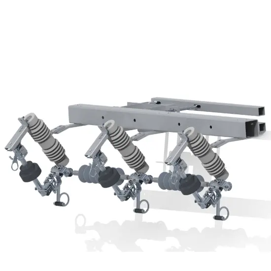 38kV Three‑Phase Mechanical‑Electronic SectionalizerIntroduction:The RDK-38/300, developed by Zhejiang Rockwell Energy for domestic and overseas 38 kV, 50/60 Hz distribution systems, coordinates with reclosers or autoreclosing breakers to confine outages to the faulted segment . Because it distinguishes transient from permanent faults by counting fault-current events, it acts only on permanent faults — transient faults reset automatically after the programmable memory time (30–300 s) (p.3). Because its electronic controller is powered by line-cur
-
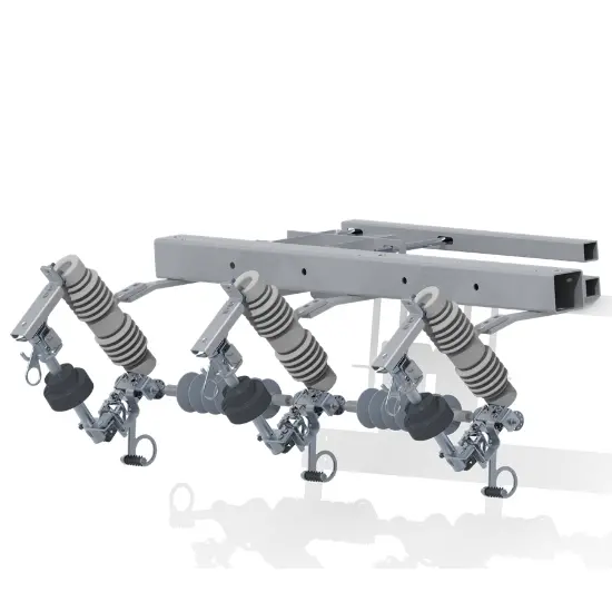 24kV Three‑Phase Mechanical‑Electronic SectionalizerIntroduction:The RDK-24/300, developed by Zhejiang Rockwell Energy for domestic and overseas 24 kV, 50/60 Hz distribution systems, coordinates with reclosers or autoreclosing breakers to confine outages to the faulted segment . Because it distinguishes transient from permanent faults by counting fault-current events, it acts only on permanent faults — transient faults reset automatically after the programmable memory time (30–300 s) (p.3). Because its electronic controller is powered by line-c
-
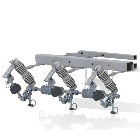 15kV Three‑Phase Mechanical‑Electronic SectionalizerIntroduction:The RDK-15/300, developed by Zhejiang Rockwell Energy for domestic and overseas 15 kV, 50/60 Hz distribution systems, coordinates with reclosers or autoreclosing breakers to confine outages to the faulted segment . Because it distinguishes transient from permanent faults by counting fault-current events, it acts only on permanent faults — transient faults reset automatically after the programmable memory time (30–300 s) (p.3). Because its electronic controller is powered by line-c