Distribution Line Fault Location and Early Warning Solution
One-sentence conclusion
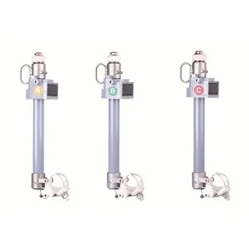
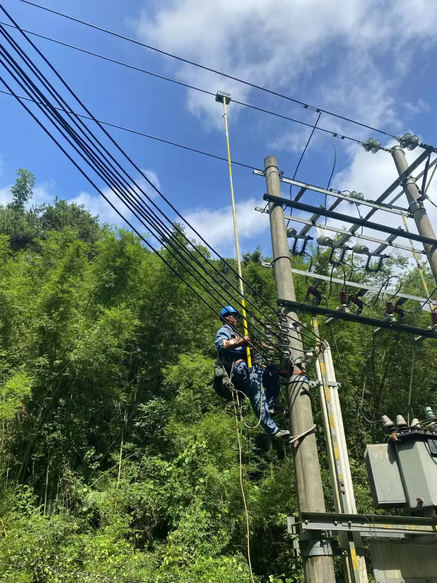
This solution deploys distribution network traveling-wave fault location terminals (one unit installed on each of the three-phase conductors, utilizing inductive power harvesting plus solar energy) to achieve the following performance metrics for 10kV overhead distribution lines: fault location accuracy within ±100 meters, segment reliability exceeding 99%, and lightning vs. non-lightning discrimination rate greater than 95%. A set is configured for main lines spanning 6–8 km, with monitoring points placed at the head and tail ends of branch lines, thereby supporting the practical implementation of distribution network automation.
I. Industry Pain Points
- Distribution network 10kV overhead lines have numerous branches and frequent faults (grounding faults, phase-to-phase short circuits, open conductors, and transient faults). Traditional FTUs primarily focus on steady-state detection and are unable to capture transient or hidden faults.
- Manual line inspection is costly and inefficient, and locating fault points relies on experience.
- Lightning strikes and non-lightning causes are overlapping, and there is a lack of data-driven identification methods.
II. Solution Architecture
Signal detection terminal (one unit installed on each of the three-phase conductors) → Communication terminal (4G all-network compatible, capable of storing full waveforms for 30 minutes, with local/remote parameter setting and software upgrades) → Master station system → Mobile handheld terminal.
- Real-time monitoring: Conductors’ current, latitude and longitude, temperature, and humidity are collected and uploaded at scheduled intervals.
- Fault Acquisition: High-speed sampling triggered by predefined conditions, recording fault current waveforms and traveling wave waveforms.
- Device self-check: Inductive power current/battery voltage monitoring, low-signal alarm, and protection against “runaway” or “lock-up”;
- The terminal is installed in a non-series bypass configuration, and single-point failure does not affect the operation of the main circuit.
III. Core Technical Indicators
|
Indicator |
Parameter |
|
Scope of application |
Adapted for different countriesOverhead lines of distribution networks |
|
Positioning error / Interval reliability |
≤±100m / ≥99% |
|
Lightning Identification |
Lightning strike vs. non-lightning strike >95% (including side strikes/counterstrikes) |
|
Time reference |
BDS ≤ 0.05 μs |
|
Traveling-wave bandwidth |
1kHz~2MHz; traveling-wave recording 500μs |
|
Fault current range |
1A~630A |
|
Power supply |
Inductive power harvesting + solar energy, normal current > 3A, long-term operation |
|
Protection/Lifespan/Weight |
IP66 / ≥8 years / ≤3.7kg |
|
Operating temperature |
-40~+70℃ |
|
Environmental adaptation |
Altitude ≤ 5000 m; gusts ≤ 45 m/s; GB 50545 heavy ice zone |
IV. Deployment Plan
- Main line: Install one set every 6–8 km;
- Short branch lines (≤3 km): Install one set at the head end;
- Long branch lines: Install one set at each of the head and tail ends.
V. Application Value
|
Operations and Maintenance Phase |
Traditional model |
After deploying this solution |
|
Hidden failure |
Unable to capture, hidden dangers accumulate. |
Traveling-wave transient capture, proactive warning |
|
Fault Localization |
Manual line inspection, hourly level |
≤ ±100 m, interval locking |
|
Cause Determination |
On-site experience |
Lightning/Non-lightning >95% Identification |
|
Operations and Maintenance Support |
Decentralized ledger |
Centralized management at the main station, remote upgrades |
FAQ
Q1How can branch lines be laid out most economically?
For short branch lines (≤3 km), installing a single set at the starting end is sufficient to provide coverage. For long branch lines, one set should be installed at each end to ensure dual-sided detection of fault locations. For main lines, one set is required every 6 to 8 km.
Q2Can the terminal power supply be maintained on low-load lines?
Dual-power supply featuring inductive power harvesting plus solar energy—normal current exceeding 3A is sufficient to sustain long-term operation. During periods of low load, solar energy and energy storage will provide supplemental power. The device’s self-check function will upload the inductive power-harvesting current and battery voltage.