How to Coordinate Reclosers and Sectionalizers:Protection Rules
What Is the Engineering Principle Behind Recloser and Sectionalizer Coordination in Radial Networks?
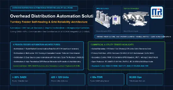
Auto recloser and electronic sectionalizer coordination is a decentralized protection strategy for overhead distribution networks that isolates faulted lateral spurs without telecommunications. The upstream recloser clears transient faults through autonomous tripping and reclosing, while the downstream sectionalizer counts overcurrent fault pulses and unlatches during zero-current de-energized intervals.
By isolating permanent branch short circuits during de-energized dead-time windows, this multi-device coordination prevents lateral failures from triggering permanent feeder lockouts, maintaining uninterruptible power supply to all upstream customers along the main backbone line.
For advanced multi-feeder grid architectures including loop automation and distributed generation (DER) directional protection, explore our companion topology guide: Recloser and Sectionalizer Coordination: 4 Feeder Protection Schemes.
What Are the Fundamental Physical and Operational Differences Between Reclosers and Sectionalizers?
Auto reclosers are primary circuit-breaking devices equipped with vacuum interrupters capable of interrupting high short-circuit currents up to 12.5kA or 20kA and executing multi-shot reclosing sequences. In contrast, electronic sectionalizers are automated isolation switches without fault-breaking interrupters, designed strictly to drop open during dead-circuit zero-current intervals.
The table below contrasts their fundamental electrical roles, standards, and operating boundaries in medium-voltage distribution systems:
Why Must Sectionalizers Drop Open Exclusively During Recloser Zero-Current Dead-Time Windows?
Electronic sectionalizers possess no internal vacuum bottles or SF6 gas chambers to extinguish high-voltage electrical arcs. If a sectionalizer attempted to unlatch its mechanical hinge while primary fault or load current was traversing its contacts, catastrophic open-air arcing would occur, causing phase-to-phase flashovers and destroying the pole-top infrastructure.
The Six-Step Autonomous Zero-Current Isolation Sequence
- Primary Short Circuit Inception: A downstream permanent fault occurs along a wooded lateral line. Fault current surges through both the substation recloser and the branch sectionalizer.
- Pickup Registration and Harmonic Filtering: The sectionalizer micro-controller senses current exceeding its programmed threshold (Gear 1 to 7), verifies genuine fault inception, and suppresses false transformer inrush pulses.
- Upstream Fast Tripping (Shot 1): The upstream recloser trips instantaneously on its fast TCC curve (for example, within 30ms to 50ms) to extinguish transient lightning or tree branch brushings.
- Line Current Cessation and Pulse Counting: As the recloser vacuum bottle opens, line current drops to zero. The sectionalizer senses current cessation and increments its internal memory register to Pulse Count 1.
- Recloser Dead-Time Interval: During the 0.5s to 2.0s de-energized reclosing interval, the entire distribution circuit remains completely de-energized.
- Delayed Second Shot and Dead-Circuit Mechanical Unlatching: If the fault is permanent, the recloser recloses into the fault and trips on its delayed slow curve (Shot 2). The sectionalizer registers Pulse Count 2. Because Count 2 equals its preset threshold, the sectionalizer fires its release solenoid during this zero-current window. The conductive tube drops open gravitationally, isolating the faulted branch before the recloser executes its final reclose onto a clean trunk.
How Is the 80 Percent Pickup Current Margin Calculated and Applied to Prevent Coordination Failure?
The minimum actuating pickup current of an electronic sectionalizer must be set to equal or less than 80 percent of the minimum trip current of the upstream recloser. This mandatory 20 percent engineering margin absorbs instrument transformer tolerances, micro-controller measurement discrepancies, and load fluctuations, ensuring the sectionalizer always detects faults.
Mathematical Derivation and Setting Criteria
- Minimum Operating Criterion: Sectionalizer Pickup Current <= 0.80 x Upstream Recloser Minimum Phase Trip Current
- Practical Distribution Engineering Example:
- Upstream Recloser Minimum Phase Trip Setting: 200 A
- Calculated Maximum Allowable Sectionalizer Pickup: 200 A x 0.80 = 160 A
- Configured RDK Sectionalizer Dial Setting: Gear 4 (160 A)
- Why the 80% Threshold Is Non-Negotiable: If a protection engineer inadvertently sets the sectionalizer pickup equal to or higher than the recloser trip value (for example, both set at 200A), transformer CT ratio variances of plus or minus 5 percent could cause the upstream recloser to trip while the sectionalizer fails to count. In that scenario, the sectionalizer never unlatches, forcing the upstream recloser into permanent lockout and blacking out thousands of innocent customers.
How Does the N Minus One Counting Rule Ensure Lateral Faults Are Isolated Before Recloser Lockout?
The sectionalizer fault counting threshold must be programmed strictly to N minus one, where N represents the total operational trip shots of the upstream recloser prior to permanent lockout. This fundamental rule guarantees that lateral fault isolation occurs before the upstream recloser reaches its final shot, allowing successful feeder restoration.
Typical Branch Coordination Topology Matrix
Upstream Recloser Curve and Memory Reset Requirements
- Minimum Delay Duration on Downstream Shots: To ensure the sectionalizer microprocessor reliably verifies fault current and current cessation, the upstream recloser delayed curves must sustain fault current for at least 0.15s to 0.5s.
- Memory Reset Duration: The sectionalizer memory reset timer (adjustable from 30s to 300s) must exceed the cumulative duration of the upstream recloser complete multi-shot cycle. If reset time is too short, counts will clear prematurely during prolonged reclosing sequences.
Why Use Three-Phase Ganged Mechanical Electronic Sectionalizers to Eliminate Single-Phasing?
When an ordinary single-phase sectionalizer drops open on a single-phase-to-ground fault along a three-phase branch, the remaining two healthy phases continue supplying power. This abnormal operating state, known as single-phasing, injects massive negative-sequence currents into downstream delta-wye distribution transformers and industrial induction motors, causing catastrophic thermal burnouts.
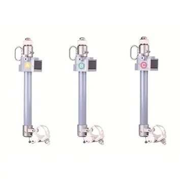
To permanently eradicate single-phasing risks on commercial and industrial laterals, RW Energy manufactures the Three-Phase Ganged Mechanical Electronic Sectionalizer (RDK-3P Series). Engineered on a heavy-duty structural steel crossarm, this configuration incorporates an insulated mechanical trip linkage shaft bridging all three phase poles. When an overcurrent fault occurs on any single phase, its micro-controller arms its release logic and unlatches its solenoid strictly during the upstream recloser zero-current dead-time window. The mechanical trip shaft instantly drives all three phase tubes to drop open simultaneously within 30ms, achieving clean three-phase physical isolation and completely protecting downstream motor loads.
How Does Decentralized Protection Operate in Remote Rural Grids Without Cellular Signals Versus Urban Smart Grids?
In remote rural, desert, and mountainous networks without cellular telemetry, distribution feeder reliability relies entirely on autonomous local coordination between reclosers and sectionalizers using electrical thresholds and counting logic. Conversely, urban smart grids utilize 4G/5G communications to feed centralized SCADA systems for automated fault location and remote switching.
Comparative Operational Architecture Analysis
- Remote Uncommunicated Networks (Autonomous Local Self-Healing):
- In vast agricultural networks, forestry reserves, and developing cross-border regions, installing fiber or cellular modems at every branch pole is economically infeasible.
- The combination of a pole-mounted vacuum recloser and autonomous RDK sectionalizers provides 100 percent standalone fault clearance without telecommunications.
- Line crews quickly locate isolated faults through direct visual observation of the physical drop-out indicator from the patrol road.
- Communicated Urban and Industrial Feeders (Centralized SCADA / FLISR):
- Urban backbone lines deploy communicating reclosers and motorized load break switches linked to dispatch control centers.
- Fault detection, directional wave recording, and feeder re-routing are coordinated in real time through IEC 60870-5-104 and IEEE 1815 (DNP3) protocols.
- Autonomous electronic sectionalizers remain ideal for unmonitored lateral taps branching off these automated feeders, keeping communication bandwidth and infrastructure costs manageable.
How Does Upgrading Expulsion Fuse Cutouts to Electronic Sectionalizers Transform Utility SAIDI and SAIFI?
Replacing legacy high-voltage expulsion fuse cutouts with autonomous electronic sectionalizers eliminates recurring fuse-blowing incidents caused by transient lightning and tree contact. Because reclosers clear transient faults before sectionalizers reach their tripping counts, lateral outages are virtually abolished, driving substantial reductions in utility SAIDI, SAIFI, and operational expenses.
Measurable Operational Reliability Benefits
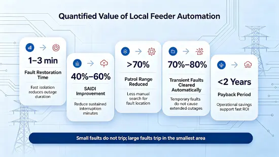
- Eradication of Spurious Outages on Transient Disturbance: Studies demonstrate that 70 to 80 percent of overhead distribution faults are transient. Fuse cutouts blow irreversibly on the first surge, whereas recloser-sectionalizer coordination absorbs temporary events without dropping open.
- Elimination of Emergency Fuse Replacement Dispatches: Eliminates the logistical nightmare of dispatching high-voltage line crews in bucket trucks across rough terrain during stormy nights merely to replace blown fuse links.
- Streamlined Protection Coordination: Eliminates tedious thermal TCC melt-curve coordination between substation breakers and branch fuse cutouts, replacing thermal grading with simple discrete pulse counting.
- Fast Capital Payback: With typical field crew dispatch expenses ranging from 300 to 800 USD per truck roll, eliminating 10 to 15 dispatches per branch achieves total capital payback within 24 months.
What Are the Real-World Protection Guidelines for Configuring RDK Sectionalizers with Reclosers?
Configuring RDK sectionalizers requires matching primary line voltage (15kV, 24kV, or 38kV), confirming continuous line current remains above 10A for autonomous CT charging, setting pickup thresholds below 80 percent of upstream recloser trip ratings, and programming pulse counts to recloser trip shots minus one.
Field Configuration Checklist for Utility Engineers
- Line Current Verification: Confirm that the protected lateral carries at least 5A of continuous load current for 15 seconds to charge the internal capacitor bank, remaining operational down to 3A.
- Pickup Current Setting (Gear 1 to Gear 7): Select the rotary dial position (16A to 480A range) ensuring the actuating current does not exceed 80 percent of the upstream recloser minimum phase trip setting.
- Pulse Counting Setting (1 to 4 Counts): Set the 3-position binary DIP switch to match upstream recloser shots minus one. For standard 3-shot reclosing schemes, configure the switch for Count 2.
- Reset Time Verification via IP68 USB Port: Connect an engineering laptop to the sealed USB interface to verify memory reset time (factory preset to 60s) exceeds the total upstream reclosing cycle.
- Inrush Suppression Verification: Verify that internal inrush harmonic filtering is active to prevent false pulse registration during upstream re-energization cycles.
What Quality Standards and Engineering Support Does RW Energy Provide for Grid Protection Schemes?
RW Energy manufactures automatic reclosers and RDK series electronic sectionalizers under strict compliance with IEEE C37.60, IEC 62271-111, IEEE C37.63-2024, and IEC 62271-102 standards, verified by comprehensive independent laboratory type-test certifications. All units include a standard 5-year manufacturer warranty, with dedicated engineering coordination support.
Complete Technical Support and Logistics Capabilities
- Standards Compliance: Certified to IEEE C37.63-2024 and IEC 62271-102 for electronic sectionalizers, and IEEE C37.60 / IEC 62271-111 for automatic reclosers.
- Environmental Ingress Sealing: Sectionalizer micro-controller enclosures and configuration ports tested and sealed to IP68 in accordance with IEC 60529.
- Comprehensive 5-Year Warranty: Full manufacturer warranty covering vacuum interrupters, electronic controllers, and mechanical release mechanisms.
- Protection Coordination Studies: In-house utility protection engineers provide customized coordination curve studies and setting verification for international power utilities and EPC contractors.