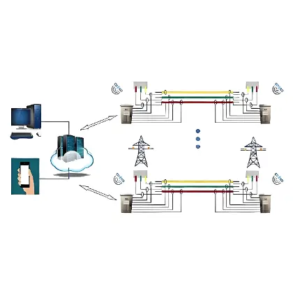
Detailed Solution for Reactive Power Compensation with High-Capacity Collection and Low-Capacity Compensation
1. Scheme Introduction
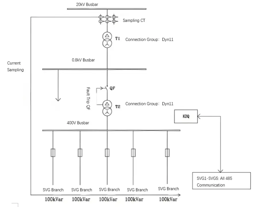
In the current electrical industry, SVG is widely adopted for reactive power compensation in high‑voltage electrical systems such as 6kV, 10kV, 20kV and 35kV. Two compensation topologies are commonly used: direct grid‑connection type and transformer step‑up type.
For applications with relatively small compensation capacity, the transformer step‑up SVG scheme is more cost‑effective and thus widely applied. This scheme was developed to address low power factor in high‑voltage power supply systems at the lowest possible economic cost according to on‑site requirements.
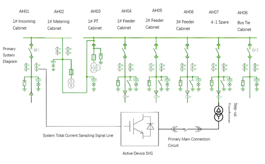
A step‑up SVG reactive power compensation system mainly consists of a low‑voltage SVG compensation cabinet (400V/690V/800V), a step‑up transformer, high‑voltage side current sampling signals and other auxiliary electrical components. The low‑voltage SVG detects system voltage and current in real time, quickly outputs compensating reactive current, which is then stepped up to the high‑voltage side via the transformer to compensate high‑voltage reactive power, thereby improving the power factor of the high‑voltage busbar.
2. Primary Schematic Diagram
3. Notes and Instructions
The primary voltage of the step-up transformer must match that of the high-voltage system, and the secondary voltage must be consistent with the rated voltage of the selected SVG.
The connection modes of the step-up transformer can be Dyn11, Dyn0, or Yyn0.
The step-up transformer can be newly installed dedicated for the SVG, or an existing on-site transformer can be used as the step-up transformer.
The total system current sampling can be taken from the main incoming cabinet or the metering cabinet. The specific location shall be determined according to the on-site sampling feasibility.
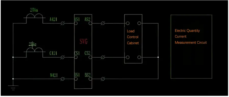
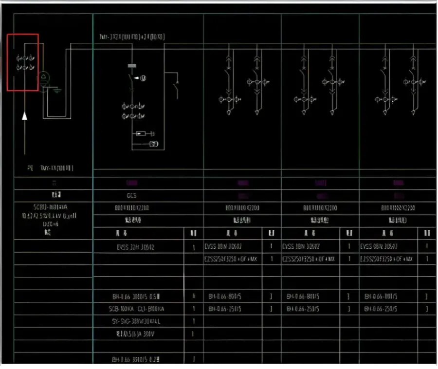
For high-voltage current sampling, some systems are equipped with one current transformer for each phase (A, B, C), while others only have CTs on phases A and C. For systems with three CTs, the current sampling wires can be directly connected to the SVG current transformer terminals. If only phase A and C CTs are available on-site, the B-phase current can be constructed synthetically, and then the three-phase current signals can be connected to the SVG. A wiring primary schematic example is shown below:
4. On-site Application System Diagram
System Main Connection Diagram (Taking 500kvar as an Example)
Deployed Equipment
-
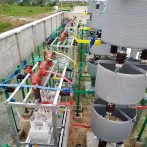 High-Voltage Reactive Power Compensation Device – Outdoor Frame TypeThe RWTBBSeries High-Voltage Reactive Power Compensation Device – Outdoor Frame Typeis designed for6kV, 10kV, 24kV, and 35kV three-phase power systems.It provides effective reactive power compensation to: Stabilize and balance network voltage Improve overall power factor Reduce energy losses in the distribution network Enhance power supply reliability and qualityEngineered for outdoor applications, this frame-structured compensation device ensures durable operation and high efficiency
 -
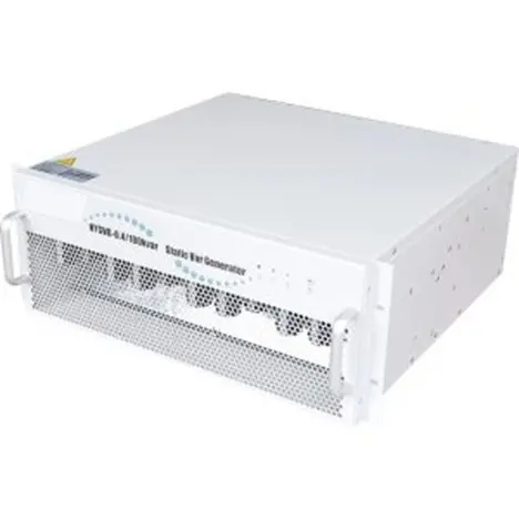 High‑Performance Static Var Generator (SVG)The RWSVG Static Var Generator is designed to provide real-time reactive power compensation through advanced self-commutated bridge technology. By connecting the bridge circuit in parallel with the power grid through a reactor, the device precisely regulates the phase angle and amplitude of the AC output voltage, or directly controls the AC-side output current. This enables the SVG to generate the required capacitive or inductive reactive current, ensuring fast, accurate, and stable dynamic reac
Reference Projects
-
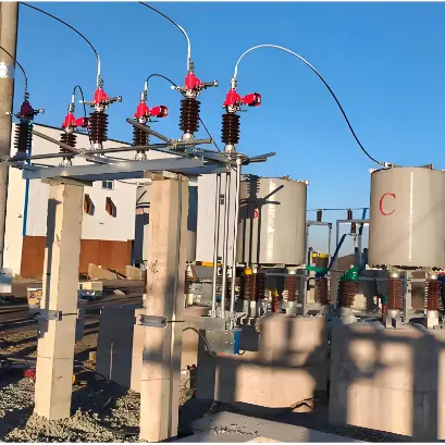 Mongolia South Gobi Coal Washing Plant 35 kV Power Quality Success StoryThe 35 kV power quality improvement project at a coal washing plant in South Gobi Province, Mongolia, is a dedicated retrofit addressing the severe harmonic pollution caused by the concentrated connection of variable-frequency-drive (VFD) equipment in the coal washing industry. A 5000 kvar H5 filter compensation bank was installed to deliver harmonic mitigation and reactive power compensation in one.Since commissioning, the dominant 5th harmonic has been effectively filtered, harmonic distortion
 -
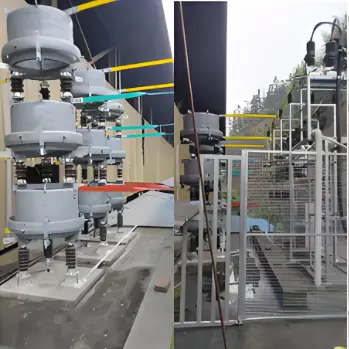 Jiangsu Suqian Rongxin Metal Products Power Quality Improvement Project-A success story in medium-frequency furnace harmonic mitigation and power quality improvementThe Jiangsu Suqian Rongxin Metal Products power quality improvement project is a dedicated retrofit addressing the severe harmonic pollution caused by the concentrated connection of nonlinear loads such as medium-frequency furnaces in the metal products industry. An H5+H7+H11 filter compensation bank with a total capacity of 17550 kvar was installed to deliver harmonic mitigation and reactive power compensation in one.Since commissioning, the dominant 5th, 7th and 11th characteristic harmonics h
 -
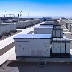 Angola Dadi Energy Storage 35 kV Power Quality Improvement success storyThe Angola Dadi Energy Storage power quality improvement project is a 35 kV power quality retrofit implemented on an existing energy storage plant. On-site nonlinear, high-harmonic loads such as inverters — power conversion systems (PCS) — are densely concentrated, a typical harmonic-source-intensive scenario in which harmonic pollution seriously hampers production efficiency and product quality.An H5+H7 filter compensation bank with a total capacity of 7500 kvar was provided to deliver harmonic
 -
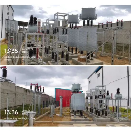 Abidjan 35kV Substation High Voltage Reactive Power Compensation Project: A Successful Case Study01 Project Overview1.1 Project BackgroundIn March 2026, RW Energy successfully delivered and deployed four sets of RWTBBX-35-2500/208.4-BLW high-voltage reactive power compensation devices for the 35kV substation upgrade project across core urban substations in Abidjan, Côte d’Ivoire, with stable and reliable operation confirmed post-installation.Climate Adaptation DesignSpecifically engineered for West Africa’s harsh tropical environment, the equipment integrates IP54-rated ca