Electrical design and protection coordination solution for Solid-State Transformer (SST) systems
I. Technical Bottlenecks in SST System Integration
Multi-Cabinet Coordination Timing Mismatch
The power electronic protection response of the power cabinet (SST) operates at the microsecond level, while the relay protection of the high-voltage cabinet operates at the millisecond level. This timing discrepancy creates a "blind zone" in protection coordination during faults, exposing power semiconductor devices to risks of overvoltage and overcurrent damage.
The inherent breaking time of the high-voltage circuit breaker (30–60 ms) is far slower than the withstand limit of IGBT/SiC devices in the power cabinet (<10 μs). Therefore, the SST system must implement autonomous current-limiting protection before the high-voltage cabinet can act.
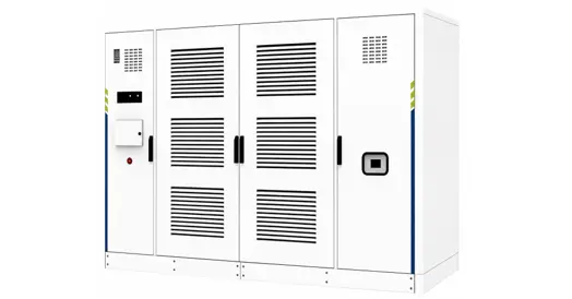
RW-SST Series Modular Solid State Transformers
Redundant and Complex Signal Interaction
A large number of hardwired inter-cabinet signals exist (e.g., disconnector status, earthing switch status, various fault alarms), resulting in complex control cable routing and overcrowded terminal blocks between cabinets.
The absence of a unified fault classification mechanism leads to ambiguous protection strategies, with response actions for different fault types relying on on-site manual judgment.
Coupling Conflicts in Power Supply and Cooling System Design
The PT (potential transformer) of the high-voltage cabinet can supply approximately 500 VA of control power, but the cooling fan power consumption can reach the kilowatt level. If fully reliant on external power supply, an additional low-voltage incoming feeder would be required, increasing system cost and footprint.
Under the forced-air cooling scheme, fan power consumption is not accounted for in overall system efficiency calculations, potentially compromising the SST system's target efficiency of 98%.
II. Core Solutions and Technical Breakthroughs
(A) Three-Tier Collaborative Protection System Design
The SST system implements a three-tier protection architecture with independent operation and graded coordination:
Tier 1 – Hardware Protection (Power Cabinet / SST System)
Executed at the microsecond level (<10 μs) through power electronic modulation for short-circuit current limiting and active IGBT/SiC pulse blocking. This tier takes priority to safeguard power semiconductor devices, acting faster than the high-voltage cabinet protection.
Tier 2 – Electrical Protection (High-Voltage Cabinet)
Operates at the millisecond level (30–60 ms) via five-prevention mechanical interlocking and microcomputer-based protection, enabling autonomous blocking and fault isolation. This ensures equipment safety and automatically disables remote operation under fault conditions.
Tier 3 – Software Protection (Main Control Unit)
Operates at the second level by aggregating signals from both power electronic hardware protection and electrical equipment protection, subjecting them to secondary logic-based judgment. This delivers full-system graded protection management and prevents maloperation or failure to trip.
Key Breakthrough: The "independent protection, graded coordination" mechanism enables microsecond-level hardware protection to act first, filling the millisecond-level "time blind zone" of the high-voltage cabinet. The three tiers coordinate sequentially and serve as backup for one another.
(B) Signal Acquisition and Interface Streamlining Design
Design Principle: "Communication as primary, hardwired points as secondary, streamlined interfaces, redundancy avoidance, resource sharing"
High-Voltage Cabinet Signal Acquisition Optimization
| Signal Type | Original Scheme | Optimized Scheme | Savings |
|---|---|---|---|
| Disconnector/Earthing Switch Status | Individual hardwired DI acquisition (≥4 DI points) | Read microcomputer protection data via Modbus communication | Eliminates 4 DI hardwired connections |
| Various Fault Signals | Individual DI point per fault type (≥8 points) | 1 common fault output + Modbus query for detailed faults | Eliminates ≥7 DI hardwired connections |
| Energy Storage Motor Fault | Individual DI acquisition | Acquisition removed (non-critical signal) | Eliminates 1 DI point |
| Auxiliary Monitoring (Door access, smoke, condensation, temperature, fan faults) | Intervenes in high-voltage cabinet native protection logic | Monitored by SST auxiliary system; does not interfere with high-voltage cabinet protection | Protection logic decoupled; clear division of responsibilities |
Unified Interconnection Interface Specification for Complete System
Inputs (DI): Emergency stop button, Local/Remote status, Fault reset — standardized and streamlined to core control points.
Outputs (DO): Global blocking, Status indicators, Trip output — unified to avoid redundant configuration.
Three-Tier Fault Classification Mechanism
Level 1 Fault: Emergency pulse blocking — fastest response at microsecond level — executed by power cabinet hardware protection.
Level 2 Fault: Power-limited operation (50% derating or shutdown) — decided by main control unit software.
Level 3 Fault: Alarm only; equipment continues running — logged and reported by the main control unit.
(C) Reactor and Short-Circuit Protection Optimization Design
| Technical Direction | Implementation Plan | Effect |
|---|---|---|
| Reactor Ratio Optimization | Balance current-limiting capability and operational losses; reasonably control reactor ratio parameters | Prevents efficiency degradation due to excessively high reactor ratio |
| Short-Circuit Current Limiting Method | Does not rely on reactor physical impedance; core uses power electronic modulation for current limiting | Microsecond-level response speed; superior to passive reactor current limiting |
| Sampling Bandwidth Matching | Deploy 400 kHz+ high-bandwidth Hall-effect sensors | Sampling loop and computation bandwidth match microsecond-level response requirements |
Key Breakthrough: Short-circuit protection of the power cabinet does not depend on the physical impedance of the reactor; it relies primarily on active power electronic modulation for current limiting. The protection speed far exceeds the millisecond-level response of the high-voltage cabinet, ensuring the operational safety of power semiconductor devices.
(D) Coordinated Design of Power Supply and Cooling Systems
Power Supply Coordination
SST Control Circuit: Powered by the high-voltage cabinet PT (approx. 500 VA) — PT capacity is sufficient, eliminating the need for an additional low-voltage incoming feeder.
Cooling Fan: Supplied by an independent low-voltage incoming line or SST auxiliary winding (several kW) — must be separately accounted for and incorporated into overall system power capacity planning.
Cooling Efficiency Management
Challenge: Fan power consumption can reach the kilowatt level, reducing overall system efficiency.
Solution: Optimize fan operation strategies through intelligent speed control and intermittent operation.
Target: Overall system efficiency ≥98%.
Additional Consideration: Proper planning of cooling power tap-off topology prevents efficiency calculation bias, ensuring accurate reflection of overall system losses.
(E) Resource Sharing and Redundancy Design
Sensor Sharing: High-voltage and low-voltage cabinets share voltage and current sampling points, reducing duplicate acquisition points and lowering hardware and cabling costs.
IO Resource Reservation: SST acquisition boards reserve DI/DO margins to address potential IO port shortages and facilitate future expansion.
Control Circuit Streamlining: Consolidate duplicate function points and optimize system architecture for clearer control logic and fewer failure points.
III. Key Technical Parameter Comparison
| Parameter | Conventional Solution | Rockwill SST Coordinated Solution |
|---|---|---|
| Protection Response Speed | High-voltage cabinet millisecond-level (30–60 ms); SST power devices at risk of damage | SST hardware protection microsecond-level (<10 μs); fills protection blind zone |
| Hardwired DI/DO Points | Independent acquisition for disconnector/earthing switch/various faults; ≥15 points | Streamlined to core signals; ≤6 hardwired points + communication readout |
| Fault Classification | No unified classification; ambiguous response strategies | Three-tier classification mechanism (pulse blocking / power limiting / alarm) |
| Sensor Configuration | Duplicate acquisition; separate configuration for HV and LV cabinets | Resource sharing; reduced duplicate points |
| Cooling Efficiency Impact | Fan power consumption not included in efficiency calculation | Intelligent speed control strategy; supports 98% overall system efficiency |
| Interface Standardization | Non-uniform interfaces across cabinets | Unified DI/DO specification; standardized interconnection |
IV. Engineering Implementation Safeguards
Protection Logic Verification Process
Phase 1: Consolidate power electronic and electrical protection logic; produce unified documentation
Phase 2: Output signal type checklist from microcomputer protection to support interface design
Phase 3: Confirm selection of 400 kHz+ high-bandwidth Hall-effect sensors
Phase 4: Integrated commissioning and testing of three-tier fault classification protection
Design Coordination Strategies
| Measure | Effect |
|---|---|
| Add condensation/temperature/smoke monitoring in high-voltage cabinet | Enhances equipment environmental safety protection capability |
| Configure earthing switch in low-voltage cabinet | Enables safe discharge of residual capacitance in transformer section |
| Low-voltage side disconnection upon high-voltage side power-off | Improves shutdown protection mechanism; prevents back-feeding |
| Investigate medium-voltage SVG manufacturer resources | Provides backup options for system reactive power compensation scheme |
V. Summary of Solution Advantages
Seamless Protection Coordination:Microsecond-level hardware protection fills the millisecond-level response blind zone of the high-voltage cabinet; three-tier protection coordinates sequentially.
Streamlined and Efficient Signal Interface:Communication-primary + hardwired-points-secondary approach; reduces hardwired points by over 60%; simplifies cabling.
Clear and Controllable Fault Classification:Three-tier fault mechanism defines clear response strategies; eliminates reliance on on-site manual judgment.
Cost-Effective Resource Sharing:Sensor sharing + IO reservation + control circuit streamlining; reduces hardware costs.
Coordinated Power Supply and Cooling Optimization:PT power supply + intelligent fan speed control; supports 98% overall system target efficiency.
100% Standards Compliance:Fully compliant with State Grid standardized design requirements; unified interfaces and flexible scalability.
Deployed Equipment
-
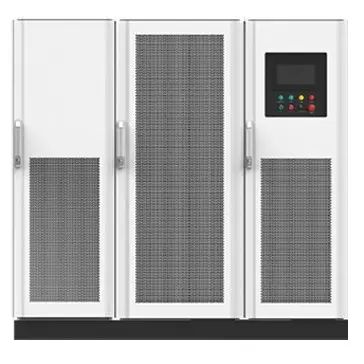 RWSST High Efficiency Solid State Transformer 8.5kV to 40.5kVRWSST Series 840–3360 kVA, featuring ultra-high efficiency, outstanding safety & reliability, flexible combination and prefabricated design.The single system adopts N+3 redundancy to form an N+X architecture, delivering higher reliability. It optimizes power supply structure, achieves higher efficiency, faster deployment and more flexible power distribution solutions.Built-in prefabricated structure, cabinets are connected via busbars, which greatly reduces installation costs such as c
 -
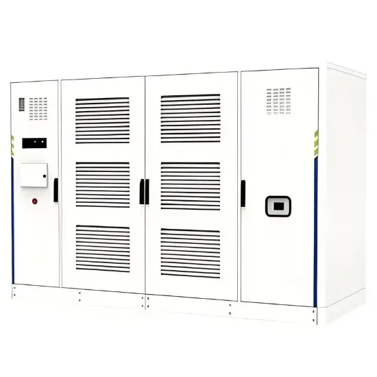 Modular Solid State Transformers for Adaptable Energy IntegrationProduct DescriptionSolid-state transformers (SSTs), also known as power electronic transformers, are based on the core concept of Power Electronic Building Blocks (PEBB). They generally employ a modular series-parallel topology to facilitate the flexible integration of varying voltage levels, capacity ratings, and forms of electrical energy, thereby enabling adaptable configurations for diverse application scenarios.FeaturesSmall size, few links, average efficiency improvement 3% (2%~5%)High fre