Hidden Danger Warning and Fault Distance Measurement System of Distribution Lines Solution
1. Scene analysis
1.1Main problems faced by distribution network lines
Traditional medium voltage distribution networks often adopt a tree like radiating topology structure, in which the power flow flows unidirectionally in the network during normal operation. With the construction of smart grids, the distribution network is formed into a multi branch, overhead cable hybrid line, circular topology structure, and modern complex distribution network topology structure containing distributed power sources. The multi branch, hybrid, circular topology structure and distributed multi power sources of the distribution network change the fault traveling wave transmission characteristics, increase the difficulty of fault feature extraction, and the uncertainty of energy flow. The reconstruction of the fault network topology structure dynamically changes, which brings great challenges to the fault state monitoring of the distribution network. Currently, the main problems faced by the distribution network lines are as follows:
Development lag and imbalance
In recent years, the construction of distribution networks has received widespread attention and investment has continued to increase. However, due to a lack of initial investment and a large number of historical debts, the development of distribution networks, especially medium voltage distribution networks, is still lagging behind compared to transmission networks. The problem of imbalanced development between urban and rural areas, as well as eastern and central western power grids, remains prominent. The current distribution network has problems of lagging development and imbalanced development, and its power supply reliability still lags behind the international advanced level, making it difficult to meet the needs of serving economic development.
Low interconnectivity and weak network structure,
The 10 kV voltage level grid structure is still weak. Nearly half of the 10 kV lines have not yet been interconnected, and the proportion of rural network interconnection is only one-third of that of urban network, indicating poor interconnectivity.
Lack of terminal devices and management platforms, low level of automation
The level of distribution automation is relatively low, and it is still in its infancy. Fault diagnosis, isolation, and recovery take a long time, making it difficult to achieve network reconstruction and self-healing. Reflected as poor mutual supply capability, the intuitive feeling is that the restoration of power supply takes a long time.
Basic data isolation and outdated information technology methods
Distribution network management involves different departments such as development, agricultural power, operation and inspection, marketing, and scheduling, with basic data scattered across different systems. The data standards and models between systems are inconsistent, and in addition, there is a lack of data sharing mechanisms. The low investment and construction level of the distribution network have led to a relative lag in the development of communication and information systems, and a lack of channels for obtaining information. Reflected as poor management refinement, data, graphics, and information cannot correspond.
The protection strategy has drawbacks and poses significant security risks
When there is a high resistance grounding fault in the distribution network, it operates with "injury". For example, a single-phase grounding fault can easily cause electric shock to personnel or poultry, and harm to humans and livestock; The power distribution network has experienced wildfire faults, high resistance grounding faults are difficult to identify, and relay protection does not trip, posing safety hazards.
The technical issues and challenges that affect the safe and stable operation of the distribution network rely on high-level distribution automation systems to solve them. The distribution network fault diagnosis system is an important component of the distribution automation system, which realizes the warning of abnormal states of distribution lines, accurate fault location, fault type identification, on-site protection, etc., providing data basis for rapid fault removal and automatic recovery of distribution automation.
1.2 Solutions for Potential Hazards Warning in Distribution Network Lines
Fault location in distribution networks, as a key function to ensure reliable and high-quality power supply, is a focus of research in distribution network automation technology. According to statistics from relevant departments of the power grid, 80% or more of power outages in the grid are caused by faults in the distribution network. To improve the automation level of the distribution network and build an intelligent distribution network, it is still necessary to conduct research and application on continuous optimization of the normal state of the distribution network and rapid positioning of fault points. The key to solving the continuous optimization of the normal state of the distribution network and the rapid positioning of fault states is to achieve automatic monitoring of the distribution network, achieve precise fault positioning and abnormal fault warning of the distribution network. It is an important part of the construction of intelligent distribution networks in smart grids, in line with the needs of national major strategies, and has great significance in promoting the strategic adjustment of the power grid industry structure, solving major bottlenecks in the development of the power Internet of Things, and improving power supply quality.
The distribution network fault diagnosis system is an important part of the distribution automation system. The distribution network fault diagnosis system based on artificial intelligence and edge computing has the functions of abnormal state early warning, accurate fault location, etc., which can effectively enhance the stability of the distribution network, speed up fault isolation, shorten fault recovery time, and improve power supply continuity. At the same time, the system can achieve web browsing, mobile SMS notifications, and guide fault inspection and troubleshooting.
2. Overall solution design
2.1Fault traveling wave positioning principle for distribution network lines
The fault location of distribution network lines is based on traveling wave positioning technology. The basic principle is shown in Figure 2.1. The double ended traveling wave positioning method is used to calculate the accurate location of the fault point based on the time difference between the traveling waves passing through adjacent monitoring points for faults and hidden dangers in the distribution line; The main station algorithm can form a network topology based on the installation line information of each monitoring point, forming a networked fault traveling wave distance measurement method. The positioning results of each monitoring point are mutually verified and fitted, effectively and accurately ensuring the accuracy of fault distance measurement results. At the same time, the system can also achieve hidden danger warning for distribution lines, with fault location accuracy up to 150m, providing strong support for operation and maintenance work and improving the self recovery ability of distribution line power supply.
Among them, L1 and L2 are the distances from the fault point to monitoring points 1 and 2, L is the distance between two monitoring points, T1 and T2 are the times when monitoring points 1 and 2 detect the traveling wave, and v is the speed of the traveling wave.
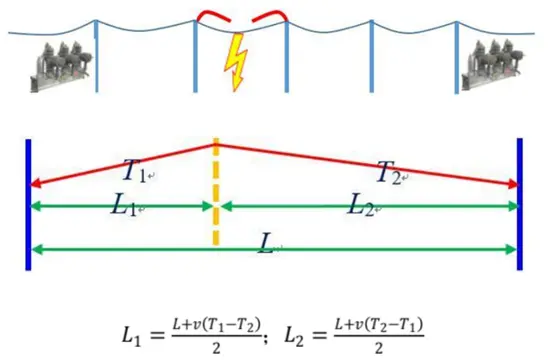
Figure 2.1 Schematic diagram of double ended traveling wave positioning
2.2 Product Description of Design Proposal
The design scheme for hidden danger warning and fault location of distribution lines includes pole mounted circuit breakers - fault distance measurement type, external distribution network traveling wave distance measurement device, distribution transformer traveling wave distance measurement terminal, and distributed distribution line fault online monitoring device. The installation configuration of the device is shown in Figure 2.2.
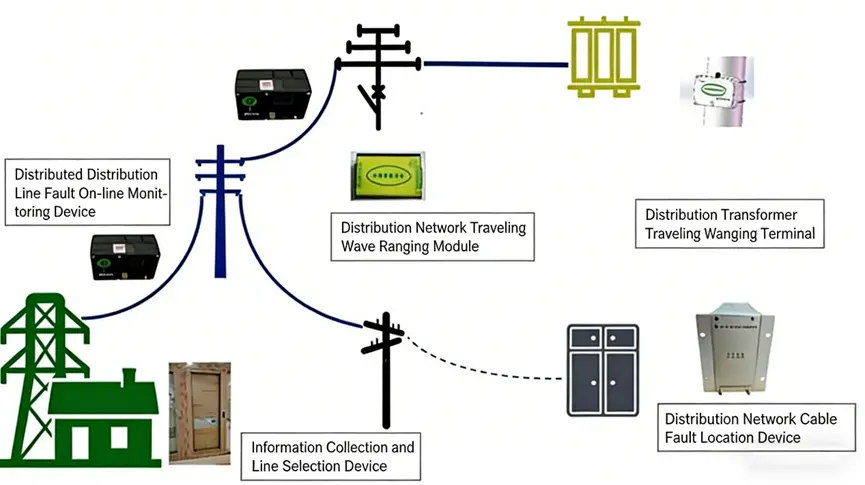
Figure 2.2 Schematic diagram of product configuration for the proposed solution
Distribution line fault location device
The external application method of the traveling wave distance measurement module in the distribution network is used for the stock renovation of existing distribution lines. It is installed between the original line circuit breaker and FTU, and connected through aviation plug-in cables for live installation. The equipment uses the same signal as the module, and all input signals are isolated. The traveling wave positioning module and FTU controller independently collect corresponding signal quantities, isolate and process them, and do not interfere with each other.
Distribution line fault location terminal
The fault location terminal of distribution lines mainly uses the principle of double ended traveling wave positioning as the fault location method. The equipment is installed on the secondary side of the distribution transformer of the distribution line, and extracts the traveling wave signal transmitted from the 10kV primary side to the low voltage side when the 10kV line fault occurs on the 400V line on the low voltage side of the distribution transformer. Comprehensively solve the blind spot problem of traveling wave monitoring at the end of line branch faults.
Distributed fault monitoring device for distribution lines
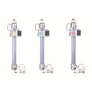
The equipment is directly installed on the wires of the distribution line, using coupling induction power supply & solar energy & battery power supply. The normal operation of the equipment requires the line load to reach 5A. It is mainly used as a backup for the final solution and is applied in situations where there are few circuit breakers or too many branches that require the installation of monitoring points.
Column circuit breaker - fault distance measurement type
The fault distance measurement type installs a traveling wave distance measurement module in the FTU, which adds precise fault location function to the traditional circuit breaker fault isolation function. The module uses the secondary signal of the circuit breaker and can collect three-phase power frequency information, traveling wave current, traveling wave voltage, 3U0 signal, 3I0 signal, etc. It can be flexibly adjusted according to the type of transformer of the circuit breaker, whether it is electromagnetic or electronic. The traveling wave distance measurement module can be adapted to various FTUs, including box type, hood type, and deep fusion FTUs. The traveling wave distance measurement module has been jointly applied on site with multiple circuit breaker manufacturers.
2.3 Overall design scheme for fault location system of distribution network lines
The distribution network fault diagnosis system consists of three parts: state monitoring execution layer, data analysis layer, and system evaluation layer. The overall architecture is shown in Figure 2.3. among which
Status monitoring layer
The status monitoring layer includes information collection devices (such as current sensors, voltage sensors, vibration sensors, temperature sensors, image acquisition, environmental sensors, switch status sensors, wired and wireless communication, etc.), status output devices (such as circuit breakers, load switches, warning indicators, etc.), to achieve real-time, online, high-precision collection and communication of multi-source information;
Data analysis layer
Data analysis layer, including early warning or fault event analysis alarm, is based on edge computing and intelligent computing to realize real-time monitoring and reliable and accurate positioning of the system's local and wide area status;
System evaluation layer
The system evaluation layer includes a structural recognition unit, a network reconstruction unit, a fault intelligent inspection unit, a fault type recognition unit, an abnormal state prediction unit, a vulnerability assessment unit, and an experience case library construction unit. Based on comprehensive analysis, it realizes abnormal state warning and hidden fault self detection of the control and protection system.
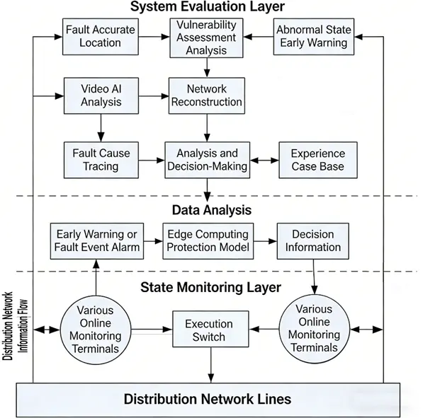
Figure 2.3 Schematic diagram of the architecture of the distribution network fault diagnosis system
Technical characteristics of the system solution:
Method for identifying fault types and extracting fault features in distribution networks
Based on the switch information, 3U0 information, power frequency electrical information, power frequency fault current and voltage recording files, high-frequency fault current recording files, hardware traveling wave information, and other information of the distribution line, artificial intelligence methods are used to extract distribution network fault characteristics, providing effective calculation basis for distribution network abnormal state warning and accurate fault location; Study the waveform characteristics of pollution, tree barriers, icing, floating objects, broken wires, high resistance grounding faults, or abnormal states of distribution network insulators, form an abnormal waveform feature fingerprint library, extract fault feature factors, and use feature factor similarity fitting to identify abnormal states of distribution lines.
Wide area fault location method based on distribution network
Reconstruct the network topology from mixed overhead cable lines, multi branch lines, and distribution network lines with variable topology structures, and use wide area network positioning methods to achieve wide area distance measurement and comprehensive optimization methods for distribution networks.
Online monitoring and warning of hidden dangers
The hidden dangers caused by insufficient insulation distance, such as tree barriers, bird damage, floating objects, insulator contamination, and icing, will all generate weak traveling wave signals before flashover. The traveling wave signal is transmitted along the wire to both ends, monitoring and analyzing weak traveling wave signals on the collection line to achieve dual end positioning and warning of hidden dangers in the collection line.
3.Data Communication and System Design Proposal
The distributed fault monitoring device, fault location device, and fault location terminal for distribution lines all use APN cards designated by the power company and 4G or 5G wireless communication methods.
It is recommended to build a distribution network fault diagnosis system in the city bureau. The system can be independently deployed on servers or distribution network cloud main station platforms, and can be connected to the property management platform through communication protocols such as MQTT and HTTP for data collection, achieving city wide distribution network fault diagnosis. The system can be integrated with the distribution network automation system.
4.The principle for selecting installation points
distribution network traveling wave positioning products is relatively low compared to transmission lines. The voltage level of distribution lines is low, and the amplitude of fault traveling wave signals is relatively low. Moreover, every time a wave impedance discontinuity point (such as the T contact of the line, the connection point between the cable and the overhead line) passes through, the traveling wave signal will undergo refraction and reflection, and the amplitude of the traveling wave signal will decrease. In order to ensure that the fault traveling wave signal can be detected by the monitoring device when it is transmitted to the monitoring device, the monitoring device generally follows the principle of installation spacing of 3-5km for point selection and installation. The specific requirements are as follows:
When automatic switches are installed on the feeder and at the T-junction of the line, FTU traveling wave distance measuring terminals are preferred. Generally, a set of traveling wave positioning devices is installed near the circuit breaker at the beginning and end of the line, and the installation in the middle of the line depends on the length of the line and the condition of the branch lines. If there are no branch lines in the middle, a set can be installed at intervals of about 5 kilometers. If there are multiple branches, a set should be installed at a maximum interval of 3 branches (short branches with a length less than 200 meters can be ignored). When there are multiple branch lines in the middle, the distance between monitoring devices should not exceed 3 kilometers.
Select distribution transformers and install traveling wave distance measurement terminals at a distance of about 1 kilometer at the front and end of the branch lines, with no more than 2 intermediate sub branch lines recommended.
When there are multiple distribution transformers to choose from near the same installation point, priority should be given to selecting the transformer with larger capacity to install the traveling wave distance measurement terminal.
5. Detailed design scheme for hidden danger warning and fault location of distribution lines
The following are 5 distribution lines as pilot lines: as shown in Figures 5.1-5.5.
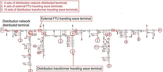
Figure 5.1 Pilot Route 1
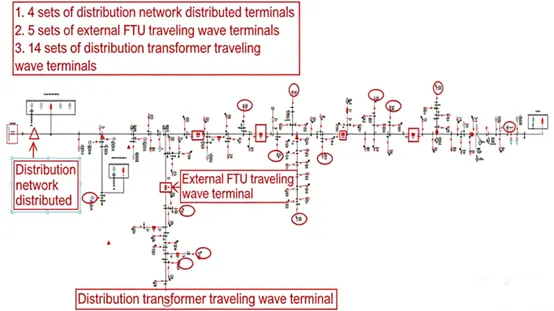
Figure 5.2 Pilot Route 2
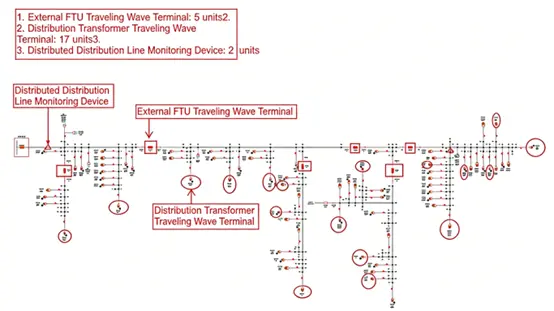
Figure 5.3 Pilot Route 3
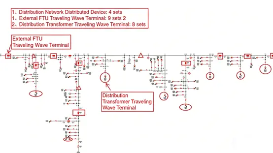
Figure 5.4 Pilot Route 4
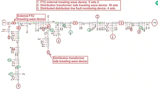
Figure 5.5 Pilot Route 5