Ultra-Fast Current Limiter (FCL): A Revolutionary Solution Featuring Millisecond-Level Interruption and Economic Benefits
1.Overview: Redefining Speed and Economics in Short-Circuit Protection
This solution focuses on an ultra-fast short-circuit current limiting device, designed to fundamentally address the growing challenge of excessive short-circuit currents and ensure the safety of power grids and equipment.
1.1 Core Features
Ultra-Fast Interruption Speed: Detects faults and limits current within 1 millisecond, effectively restraining the short-circuit current before it reaches its prospective peak.
High Interruption Capacity:
Suitable for 12kV/17.5kV systems: Maximum breaking capacity of 210kA (RMS).
Applicable to 24kV/36kV/40.5kV systems: Maximum breaking capacity of 140kA (RMS).
1.2 Core Advantages
Economic Efficiency: Operates in parallel with current-limiting reactors to deliver the most cost-effective limiting solution. Avoids replacing entire switchgear panels or transformers due to increased short-circuit currents, significantly reducing investment in new or upgraded substations.
Broad Compatibility: Ideal for interconnecting switchgear and substations; in many scenarios (e.g., parallel operation of multiple transformers), it is the only feasible technical solution.
Exceptional Reliability:
Over 60 years of global operational experience (invented in 1955), validated in thousands of projects worldwide.
Statistics from nearly 4,000 units show an average operation frequency of only once every four years, demonstrating stable and reliable performance.
2.Key Technical Q&A
No. |
Key Question |
Core Answer |
1 |
What is peak short-circuit current? |
The maximum instantaneous value during the first cycle after a short-circuit fault occurs, resulting from the superposition of periodic and non-periodic components. It generates enormous electromagnetic forces (testing dynamic stability) and heat (testing thermal stability). |
2 |
Why limit peak short-circuit current? |
Peak currents exceeding equipment-rated withstand parameters can damage switchgear, circuit breakers, current transformers, and cable connectors through powerful electromagnetic forces. |
3 |
How to adapt to parallel operation of multiple transformers? |
For switchgear with a withstand capability of 2Ik, in a system with four transformers (4Ik) in parallel, perfect adaptation can be achieved by installing fast current limiters between bus sections (e.g., between sections 1-2 and 3-4). |
4 |
What are the tripping criteria? How to avoid false trips? |
The control unit simultaneously monitors instantaneous current (I) and rate of current rise (di/dt). A trip is triggered only when both exceed set thresholds. This dual criterion ensures only hazardous short-circuit currents are interrupted, while general faults are handled by downstream circuit breakers. |
5 |
How to maintain after operation? |
The core operating component (conductive bridge) features a modular design and can be returned for repair. Only the internal conductive core, inductive filler, and parallel fuses need replacement; other components are reusable, ensuring very low maintenance costs. |
3.Core Functions and Value
3.1 Core Function
Detects and limits faults during the initial rising stage of short-circuit current (within 1ms), effectively preventing damage to power equipment due to insufficient dynamic and thermal stability. It perfectly compensates for the inherent limitations of traditional circuit breakers—"slow to act and unable to suppress the first half-wave peak current."
3.2 Comparative Advantages
Comparison Object |
Advantage Details |
Traditional Circuit Breakers |
Breakers take tens of milliseconds to interrupt, unable to avoid the impact of the first peak current. This limiter responds within 1ms, restricting the actual peak short-circuit current to a lower level. |
Current-Limiting Reactors |
Avoids voltage drop, active losses (copper losses), and reactive losses associated with reactors in continuous operation. Also eliminates the need to address generator regulation issues caused by reactor integration. |
3.3 Applicable Scenarios
Power plants
Large industrial grid substations
Specific key circuits/scenarios: Transformer/generator feeder circuits, bus tie sections, reactor bypass applications, and interconnection points between grids and captive power sources.
4.Structure and Design
4.1 Overall Composition
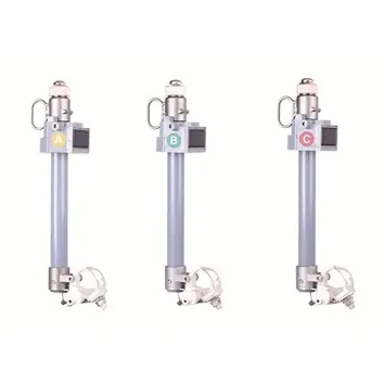
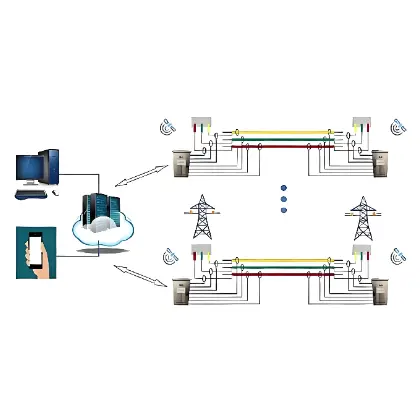
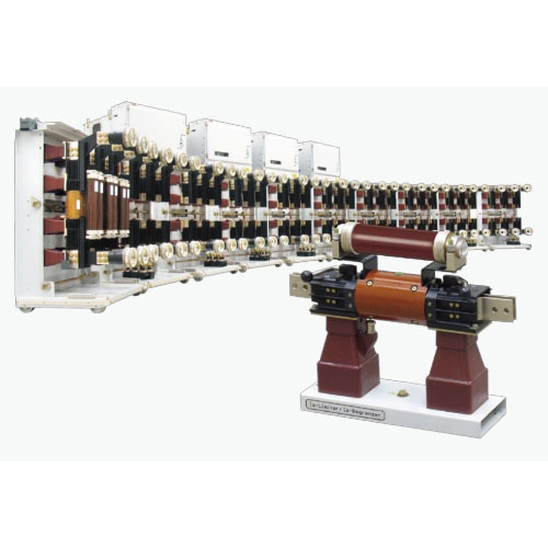
The three-phase AC system fast current limiter consists of:
3 conductive bridge bases
3 conductive bridges
3 matching current transformers
1 control unit
4.2 Key Component Details
Component Name |
Composition / Features |
Key Parameters / Rules |
Conductive Bridge Base |
Includes mounting plate, insulators, pulse transformer, and connectors with quick couplings |
- Rated current ≥2500A and voltage 12/17.5kV: Bolted connections. |
Conductive Bridge |
Conductive core and inductive filler encapsulated in an insulating cover |
Upon tripping, the inductive filler is triggered, driving the conductive core to break rapidly at its pre-cut; current then transfers to the parallel fuse. |
Matching Current Transformer |
Bushing or block type, series-connected in the main circuit |
Features a gapped core (high overcurrent factor, low remanence) and shielded primary/secondary windings (low impedance) to ensure measurement accuracy and speed. |
Control Unit |
Includes power supply, control, indication, and anti-interference units |
- Dimensions: 600mm (W) × 1450mm (H) × 300mm (D); weight: 100kg. |
5.Working Principle: Achieving 1ms Current Limiting
5.1 Core Composition
The device is essentially an intelligent parallel combination of two components:
"Extremely fast switch (conductive bridge)": Carries rated current during normal operation and opens instantaneously during faults.
"High-breaking-capacity fuse": Ultimately interrupts the high current after the switch opens.
5.2 Operation Sequence
Detection: Matching current transformers (CTs) continuously collect current signals; the control unit calculates instantaneous current (I) and rate of current rise (di/dt).
Judgment: When both I and di/dt exceed set values, the control unit immediately issues a trip command (independent three-phase judgment and triggering).
Interruption: The trip capacitor discharges into the pulse transformer, triggering the inductive filler in the conductive bridge. This generates high-pressure gas, causing the conductive core to rupture at its pre-cut within 1ms.
Current Limiting: Arc resistance increases rapidly, transferring current to the parallel fuse. The fuse begins limiting within 0.5ms and extinguishes the arc completely at the next current zero, clearing the fault.
5.3 Auxiliary Units
Power Unit: Provides 150V DC power to charge the trip capacitor and supply electronic components. Includes a watchdog circuit to monitor system health.
Anti-Interference Unit: All external wiring passes through this unit, providing effective protection against external electromagnetic interference and preventing false operations.
6.Commissioning and Testing
6.1 Testing Requirements
Regular functional testing is required, which can be executed by users or ABB service engineers.
6.2 Dedicated Equipment
Simulator: Temporarily replaces the conductive bridge during testing. Its built-in neon lamp lights up upon receiving a trip pulse, indicating proper operation.
Test Plug & Test Instrument: Used to check trip output voltage and overall functionality. Features a user-friendly interface and easy operation (dimensions: 400×215×320mm; weight: 11kg).
7.Scope of Supply and Parameters
7.1 Supply Models
Model Type |
Applicable Scenarios |
Core Configuration |
Discrete Components |
For installation in existing switchgear |
3 bases + 3 conductive bridges + 3 CTs + 1 control unit |
Drawout Cabinet |
For metal-clad switchgear |
Conductive bridges mounted on withdrawable carts (with isolating switch function); CTs fixed; control unit installed in the low-voltage compartment |
Fixed Cabinet |
- For 12/17.5/24kV systems |
All components fixed inside the cabinet. For 36/40.5kV systems, the control unit is often installed in a separate control box. |
7.2 Key Technical Parameters (Example: Discrete Components)
Note: ¹ indicates forced air cooling is required; compatible with 50/60Hz frequency.
Technical Parameter |
Unit |
12kV |
17.5kV |
24kV |
36/40.5kV |
Rated Voltage |
V |
12000 |
17500 |
24000 |
36000/40500 |
Rated Current |
A |
1250-5000¹ |
1250-4000¹ |
2500-4000¹ |
1250-3000¹ |
Rated Short-Circuit Breaking Current (Max.) |
kA RMS |
210 |
210 |
210 |
140 |
8.Typical Application Scenarios
Application Scenario |
Core Issue |
Solution Value |
Parallel System Operation |
Short-circuit current from multiple transformers in parallel exceeds switchgear ratings |
1. Allows reduced system impedance, minimizing voltage drop. |
Grid-Captive Power Interconnection |
Captive generator operation causes excessive short-circuit current at the common coupling point |
The only rational solution. Can be equipped with directional tripping (requires CT at generator neutral) to ensure operation only for grid-side faults. |
Bypassing Current-Limiting Reactors |
Reactors in continuous operation cause losses and voltage drop |
Bypasses reactors during normal operation (zero loss, zero voltage drop); rapidly interrupts during short circuits, diverting current to the reactor for limiting. |
Selective Application of Multiple Units |
Selective operation required when multiple limiters are installed on multi-section buses |
Uses "current vector sum" criterion to ensure only the limiter closest to the fault operates. Supports up to 5 transformers in parallel (using 4 limiters). |
9.Service and Support
Contact Email: Support@rw-relay.com