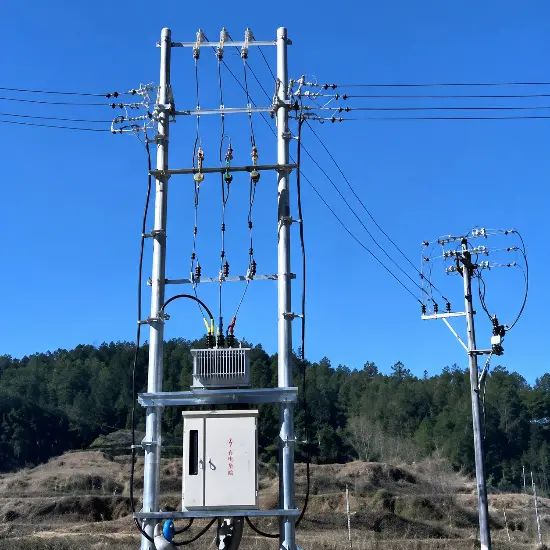
Coordinated Application Scheme for Reclosers and Drop-Out Type Sectionalizers
1. Executive Summary
This solution proposes a fault-isolation architecture based on the coordinated operation of automatic reclosers and drop-type sectionalizers, featuring “local control without communication.” It is particularly suited for rural and suburban feeders in 15 kV overhead distribution networks in developing countries and regions overseas—areas where SCADA infrastructure is weak, communication maintenance costs are high, and enhancing power supply reliability is the primary objective.
The proposal is based on two well-established sources: First, the journal article “Application of Automatic Segmenters in Distribution Network Automation” (Journal of Huangshi Institute of Technology, 2005) demonstrates the cost-effectiveness and ease of implementation advantages of local control (combining reclosers with segmenters) over remote control. Second, the field-verified RDK-15/300 three-phase electromechanical segmenter (V2.1 manual, 2026) features programmable counting, USB/DIP configuration, and self-powering from line current.
- No communication infrastructure required—fully autonomous, on-site control;
- The faulty section is automatically isolated, while non-faulty sections maintain continuous power supply.
- Low investment and operation & maintenance costs, maintenance-free, and quick deployment;
- Complies with IEC/ANSI recloser coordination practices (tripping follows a slow-speed curve, and the interrupting time is > 0.5 s).
2. System Concept and Operating Principle
2.1 Comparison between Local Control and Remote Control
There are two technical approaches to distribution network automation. Remote control relies on the coordinated operation of a master station system, substation systems, communication systems, and monitoring terminals, achieving a high degree of automation. However, this approach involves substantial maintenance efforts for the communication system and incurs high system costs, making it less suitable for medium- and small-sized urban distribution networks—especially rural power grids. In contrast, local control utilizes automated switching devices that promptly detect faults and automatically perform operations according to predefined procedures, swiftly isolating the faulty section while ensuring uninterrupted power supply to non-faulty areas. This approach does not require communication infrastructure, is simple to implement, requires low investment, delivers excellent results, and is easy to promote.
2.2 Device Role
|
Equipment |
Role in the plan |
Key competencies |
|
Recloser (substation outlet) |
Interrupt fault current and automatically reclose according to the set sequence (e.g., 1 fast + 3 slow). |
Fault interruption and automatic reclosing |
|
Drop-out type sectionalizer (on the line) |
Cumulative number of fault current interruptions; no-load trip and disconnect when the count reaches the preset value and the line voltage is lost. |
No-load isolation, counting, and memory |
The sectionalizer is an isolating device rather than a protective one: it never interrupts fault currents but only drops out under no-load conditions after being de-energized (voltage loss) by the upstream recloser. This feature makes its mechanism lightweight, cost-effective, and maintenance-free.
2.3 Sectionalizer Types and Design
Sectionalizers are categorized into two types: current-time and voltage-time. The RDK-15/300 electromechanical sectionalizer belongs to the current-counting type: its on-board microcontroller accumulates fault current events. When the preset counting cycle (1, 2, 3, or 4 times) is completed and the line voltage drops to zero, the device outputs an excitation signal that actuates the electromagnetic actuator, releasing the trip latch and causing the conductive components to drop, thereby isolating the faulty section. The memory time defines the duration for which the count is retained; the reset time (30 to 300 seconds) enables the device to return to its initial state prior to the fault after a transient fault has been cleared.
The control core implements fault current detection, undervoltage detection, and counting logic; three-phase interlocking is ensured through mechanical interlocks.Use when wireless interconnection is required.Low-power wireless synchronization (such as the nRF401 module) ensures that the three-phase segmenters drop simultaneously.
2.4 Synchronize timing
Fault occurrence → Upstream recloser trips (either fast or slow curve) → The counter for all sectionalizers carrying fault current increments by one → Line voltage drops → Sectionalizers whose counters reach the preset value trip while in no-load condition → The recloser recloses, restoring power to the non-faulted sections, while the isolated section remains de-energized. In the case of a transient fault, all counters reset after their memory time expires, and the line returns to normal operation without any further action.
Hardware Highlights: The control system is powered by a current transformer (I1, I2A, I2B) for sampling, a rectifier and voltage-stabilization circuit, and driven by thyristor electronic switches (SR1, SR2). The interrupt handling process includes an external interrupt INT0 (which increments the fault count and starts timer T1), a serial receive interrupt (which processes incoming commands), and a T1 timer interrupt (which sets a 1-second flag). The trip control module triggers the actuator to open the circuit breaker and sets an opening flag when either “the number of fault currents reaches the set value” or “a trip command is received,” provided that “the line voltage has dropped.” Typical memory delay is 15 seconds, and state recovery takes 30 seconds.
3. Technical Design Basis
3.1 Recommended Equipment Parameters (RDK-15/300 Grade)
|
Parameter |
Numerical value |
Note |
|
Rated Voltage / Frequency |
15 kV / 50-60 Hz |
Frequency optional |
|
Rated continuous current |
300 A |
— |
|
Starting (action) current |
16 – 480 A programmable |
The setting must be more than 20% lower than the recloser’s trip current. |
|
Counting frequency |
1 / 2 / 3 / 4 Programmable |
Reduce the recloser setting count by one. |
|
Reset time |
30 – 300 s, resolution 1 s |
Memory retention after transient faults |
|
Current measurement accuracy |
± 5% |
— |
|
Main circuit resistance |
≤ 300 μΩ |
— |
|
Short-time withstand current |
8600 A / 15 cycles (60 Hz); 4000 A / 1 s; 3200 A / 3 s |
Symmetry |
|
Transient / Inrush Current |
12 kA asymmetric / 65 kA |
— |
|
Self-powered |
Line current > 5 A sustained for 15 s to fully charge; ≥ 3 A to keep running. |
No external auxiliary power supply required |
3.2 Comply with the setting rules (mandatory requirements)
|
Rules |
Requirements |
Purpose |
|
Current margin |
The circuit breaker’s inrush current ≤ 80% of the recloser’s inrush current (applicable to both phase faults and ground faults). |
The sectionalizer detects faults before the recloser. |
|
Counting margin |
Number of segmenter counts = Number of recloser settings − 1 (e.g., for a 1-fast-3-slow recloser, the segmenter can count up to 3 times). |
Complete isolation before the final overlap. |
|
Timing margin |
The recloser must trip at a slow-speed curve (breaking time > 0.5 s). |
The circuit breaker trips under no-load conditions but never interrupts fault currents. |
Selection guidelines: For customer incoming lines, a single-count setting is generally recommended—most faults in customer substations are permanent. For branch connection points on overhead lines, a two- or three-count setting is recommended—approximately 80% of faults on overhead lines are transient, which facilitates coordination and optimal matching among sectionalizers.
3.3 Environmental and Installation Conditions
- Ambient temperature: -40 ℃ ~ +60 ℃ (suitable for tropical, desert, and cold regions);
- Altitude: ≤ 2000 m; Wind pressure ≤ 700 Pa; Ice thickness ≤ 1 mm;
- External insulation contamination level: Class IV; Controller USB interface protection rating: IP68;
- Perform pole-mounted installation according to the bracket installation diagram; operate the hook rod.
4. Application Architecture
4.1 Feeder Configuration
Typical configuration: A recloser is installed at the substation outlet, with a protection sequence set to 1 fast + 3 slow. Six automatic drop-out sectionalizers—F1 through F6—are deployed on the branch feeders, dividing the line into seven segments labeled L1 through L7. Count settings: F1 = 3 times; F2, F3, and F5 = 2 times each; F4 and F6 = 1 time each.
|
Equipment |
Counting |
Coverage section |
|
F1 |
3 Next |
L2 (near the power supply side, with the highest number of reclosures) |
|
F2, F3, F5 |
2 Next |
Middle section branch line |
|
F4, F6 |
1 Next |
End branch |
4.2 Fault Scenario Simulation
|
Case |
Fault point |
Action process |
Recovery Section |
|
E1 |
L5 segment |
F4 (1st count) drop, isolate L5 segment |
L1–L4, L6, L7 |
|
E2 |
L6 segment |
F5 (2-count) drop isolation L6; automatic reset for transient faults. |
L1–L5 (permanent fault) / All (temporary fault) |
|
E3 |
L2 segment |
F1 (3-count) drop, isolate L2 segment |
L1 |
Branch Circuit Fault Case: A sectionalizer installed at the branch tap point, configured with a single-count function, can isolate customer-side faults (K1)—whether permanent or transient—without affecting the main feeder.
5. Benefits and Life-Cycle Costs
5.1 Reliability enhancement
- Without requiring operator intervention, fault sections are isolated within seconds—directly improving SAIDI/SAIFI metrics.
- Transient faults (accounting for approximately 80% of overhead line faults) are cleared solely by reclosers, while section switches automatically reset.
- The permanent fault is confined to the smallest section, and the vast majority of users remain supplied with power.
5.2 Cost Comparison with Remote Control Solutions
- No SCADA master station, no communication links, and no terminal maintenance—investment is merely a fraction of that required for remote control solutions.
- The separator is maintenance-free (self-powered, battery-free, SF6-free, and requires no auxiliary power supply);
- It’s installed on the standard rod and is quick to deploy; local personnel can complete debugging using a simple USB configuration tool after brief training.
5.3 Debugging and Operations
- Set the count and current range via DIP switches, or configure via USB (default admin/123, which can be modified);
- Event Log: Up to 100 entries (trip/automatic reset/manual reset, trip current, maximum/minimum current); exportable to Excel.
- The maintenance software provides trip testing, real-time status viewing, and message monitoring functions.
- The waterproof sealing of the module is critical to the device’s lifespan—parameter modifications must be performed by trained technicians.
6. Overseas Deployment List
- Standard Compliance: Reclosers shall comply with IEC 62271-111 (or, where applicable, with ANSI C37.60); sectionalizers with associated logic shall comply with IEC 60255-class relays; system design must conform to the grid regulations of the target utility company.
- Voltage/Frequency: 15 kV class, available in 50 or 60 Hz—subject to confirmation with the target power grid (if a 11/20/22/33 kV variant is required, further discussion is needed);
- Environmental verification: Confirm the on-site ambient temperature range, pollution level, altitude, and icing conditions.
- Neutral Point/Earthing: Confirm the system’s earthing method (direct earthing, impedance earthing, or neutral point ungrounded) and the coordination of the fault current trip setting for ground faults.
- Attachment configuration: load-breaking capability hook rod, hot-work line clamp kit, spare DIP module, USB test cable, and driver package;
- Training and Documentation: English manual + quick guide to the configuration tool; on-site debugging by trained personnel;
- Spare Parts Strategy: Reserve segmenters and complete installation brackets at a ratio of 10% to support rapid replacement.
7. References
- Xu Lufei, Pi Daneng, and Wang Zaiming: “Application of Automatic Sectionalizers in Distribution Network Automation,” Journal of Huangshi Institute of Technology, Vol. 21, No. 6, December 2005 (Article ID 1008-8245(2005)06-0016-03).
- Rockwill Group: “User Manual for Three-Phase Mechanical-Electronic Sectionalizer RDK-15/300,” V2.1.0, June 2026.
- Xu Layuan and Gao Yimei: "Design and Technical Applications of Unattended Substations in Rural Power Networks," China Electric Power Press, 1999.
Reference Projects
-
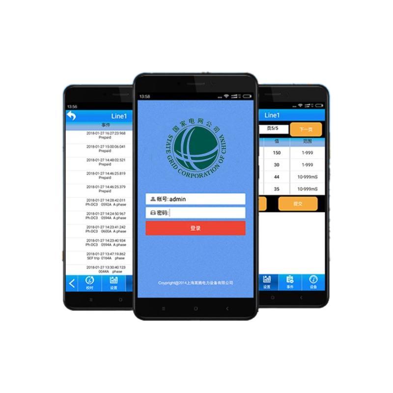 RW Energy Multi Country SMS Based Auto Recloser Controller Case StudyBreaking the communication bottlenecks in remote areas worldwide, this solution takes SMS communication as its core innovation and develops recloser controllers adaptable to multiple countries and diverse climates. Free from reliance on 4G networks, it enables rapid fault early warning and remote operation & maintenance management, helping various regions resolve distribution network operation challenges in remote areas and inject intelligent momentum into global rural power grid upgrading.0
 -
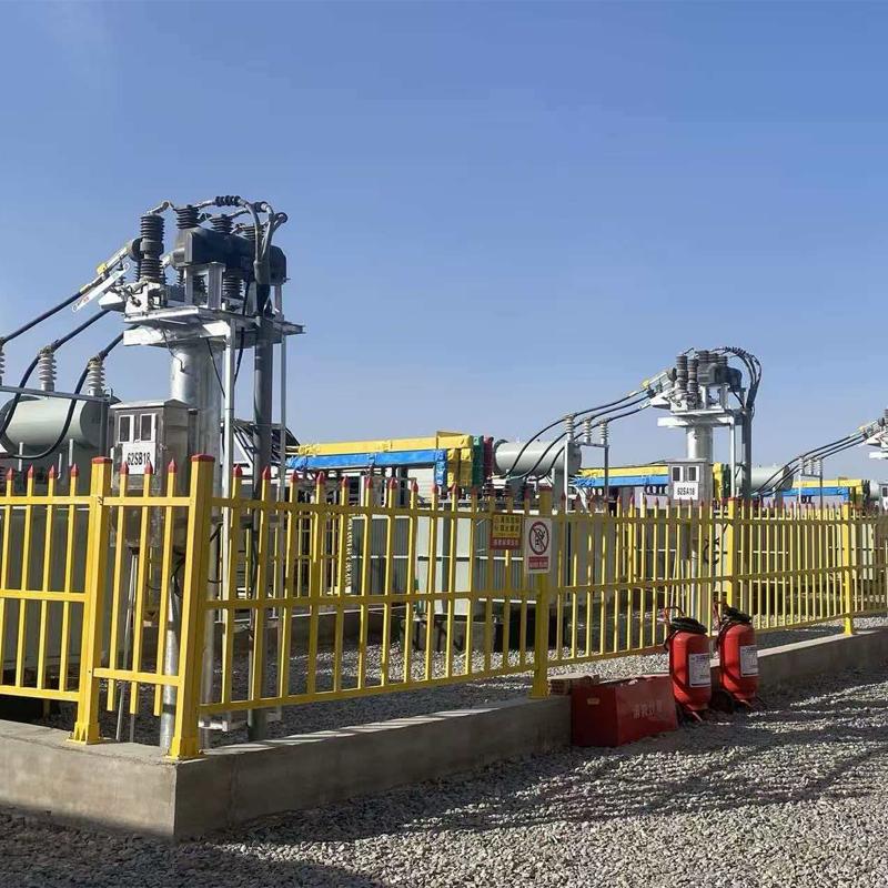 RW Energy Xinjiang Bazhou Large-scale Data Center 6 kV Industrial Grid Intelligent Power Distribution Upgrade Case StudyFocusing on the high-reliability power supply demands of data centers, this project upgrades the 6kV industrial intelligent power distribution system. It enhances anti-sandstorm and wide-temperature environmental adaptability, integrates rapid protection and remote intelligent operation and maintenance technologies, stably supports high-density computing loads, and empowers the intelligent transformation of power grids in western computing hubs.01 Project Overview1.1Project BackgroundBayingolin
 -
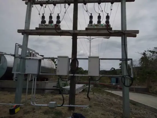 RW Energy Bangladesh 230 Units 11 kV Vacuum Circuit Breaker Intelligence Retrofit Case StudyFocusing on Bangladesh’s distribution network automation upgrade demands, the intelligent retrofitting of 230 sets of 11kV VCBs integrates intelligent control and anti-corrosion technologies. Adopting a cost-effective renewal model for legacy grids, it enables equipment reuse and efficiency improvement, advances regional distribution network digital transformation, and sets a benchmark for the intelligent upgrading of aging switchgear in South Asia.01 Project Overview1.1 Project BackgroundIn Dec
 -
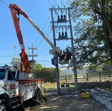 RW Energy Colombia PV Plant 35 kV Recloser Controller Project Case StudyFacing the frequency fluctuation and grid connection challenges of Colombia’s low-inertia photovoltaic power grid, this solution leverages customized recloser control and optimized frequency protection technologies to precisely adapt to the local 60Hz grid standard. It effectively addresses grid fluctuation issues under complex grid connection conditions, delivering a highly reliable and strong anti-interference grid protection solution for photovoltaic power plants and ensuring their stable and
 -
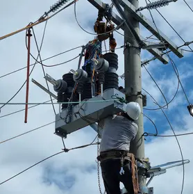 RW Energy Tanzania 325 Units 33 kV Auto Recloser Project Case StudyFocusing on the medium‑voltage distribution network upgrading demands in Tanzania, this solution adopts 325 sets of high‑reliability 33kV auto-reclosers integrated with FTU intelligent control and high environmental adaptability technologies to isolate faults and restore power supply rapidly, consolidating the stable foundation of regional power grids.01 Project Overview1.1 Project BackgroundIn 2025, 325 units of 33 kV auto reclosers were officially supplied and applied to the Tanzania medium-vo
 -
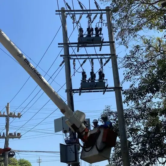 420 Units of 11 kV Automatic Reclosers for Dhaka Grid Upgrade01 General Overview: Dhaka 11 kV Distribution Grid Upgrade1.1 Project BackgroundBangladesh is currently undergoing a period of rapid economic and industrial development, and the growing demand for electricity has placed immense pressure on the local distribution networks. However, the country's existing 11 kV backbone distribution lines are facing severe equipment aging issues. The original switchgear suffers from serious mechanical wear, resulting in not only high failure rates but also sluggis