SST Flexible Interconnection Router Boosts DER Absorption Solutions
1. Industry Background and Pain Point Analysis
1.1 Industry Background
The explosive growth of distributed photovoltaics (residential + commercial & industrial) has brought three new challenges to distribution networks: reverse heavy loading at substation areas, voltage limit violations, and difficulties in renewable energy accommodation.
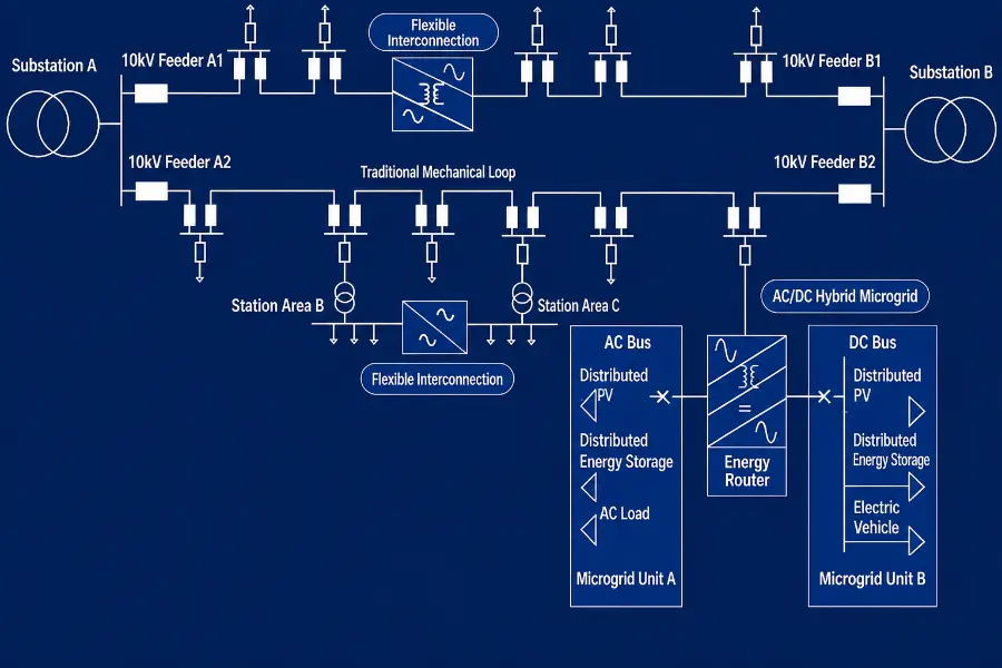
The traditional distribution network's rigid structure of "one substation area, one transformer" cannot achieve power mutual support between substation areas, resulting in the coexistence of solar curtailment and transformer overloading.
1.2 Four Major Pain Points of Traditional Distribution Networks
| Pain Point | Manifestation | Physical Root Cause |
|---|---|---|
| Difficult Accommodation | Solar curtailment in PV-rich substation areas | No power mutual support between substation areas |
| Reverse Heavy Loading | Transformer overloading in substation areas during peak PV generation | Unidirectional power distribution structure |
| Voltage Limit Violations | Voltage rise at PV concentration points | No active voltage regulation capability |
| High Losses | Long-distance power transmission | Uncontrollable power flow |
1.3 Core Differences Between Traditional and SST Flexible Interconnection (Physical Essence)
Traditional Distribution Network (Rigid Substation Areas)
| Aspect | Physical Principle | Limitation |
|---|---|---|
| Independent Substation Areas | One transformer per substation area | No power mutual support |
| Unidirectional Power Flow | Source → Load | PV reverse flow becomes a problem |
SST Flexible Interconnection (Flexible Substation Areas)
| Aspect | Physical Principle | Advantage |
|---|---|---|
| Common DC Bus | Multiple substation area SSTs interconnected | Power mutual support capability |
| Bidirectional Power Flow | SST controllable bidirectional | Local PV accommodation |
Physical Essence: The SST power router connects multiple substation areas to a common DC bus, allowing PV-rich substation areas to transfer power to power-deficient areas. This is the physical foundation for achieving +18% distributed PV accommodation.
2. Solution Overview and Value Proposition
2.1 Solution Definition (BLUF)
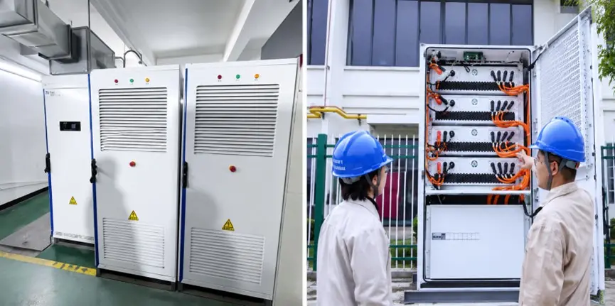
The SST Direct-Attached Flexible Interconnection Power Router (1.5/2.0MW, AC10kV/DC±10kV) enables flexible interconnection of multiple substation areas through a common DC bus:
-
Distributed PV accommodation +18%
-
Network losses reduced by 5%+
-
Equipment efficiency 98.7% (verified by Guangdong Power Grid)
2.2 Core Value Proposition
| Value Dimension | Quantitative Metric | Description |
|---|---|---|
| Distributed PV Accommodation | +18% | Local PV consumption |
| Network Loss Reduction | -5%+ | Flexible power flow control |
| Equipment Efficiency | 98.7% | +4% improvement over traditional solutions |
| Single Unit Capacity | 1.5/2.0 MW | Covers medium-voltage substation areas |
| Port Voltage | AC10kV/DC±10kV | AC and DC dual ports |
3. System Architecture Design
3.1 System Topology (Layered Breakdown)
Substation Area A 10kV ──► [SST Power Router A] ──┐
Substation Area B 10kV ──► [SST Power Router B] ──┼──► Common DC Bus DC±10kV
Substation Area C 10kV ──► [SST Power Router C] ──┘
                                                    ├──► Substation Area Loads
                                                    ├──► Distributed PV Integration
                                                    └──► Energy Storage Coupling Port
Topology Layer-by-Layer Explanation
| Layer | Composition | Power Flow | Design Rationale |
|---|---|---|---|
| Substation Area Access | 10kV from each substation area | Substation area ↔ DC bus | Multi-area interconnection |
| Common DC Bus | DC±10kV | Power mutual support between areas | Bidirectional power flow capability |
| Loads/Sources | Loads + PV + Energy Storage | Bidirectional | Local accommodation |
3.2 Flexible Power Flow Control Principle
Traditional substation transformers can only perform "unidirectional step-down power transmission." The SST power router, by contrast, functions as a "controllable bidirectional power valve." By controlling the power setpoints of each port, it enables power transfer from PV-rich substation areas to power-deficient areas while actively suppressing voltage limit violations.
4. Core Equipment and Technical Parameters
| Parameter | Value | Physical Significance |
|---|---|---|
| Single Unit Capacity | 1.5/2.0 MW | Covers medium-voltage distribution substation areas |
| Port Voltage | AC10kV/DC±10kV | AC and DC dual ports |
| Distributed PV Accommodation | +18% | Local PV consumption |
| Network Loss Reduction | -5%+ | Flexible power flow control |
| Equipment Efficiency | 98.7% | Verified by Guangdong Power Grid |
5. Technical Highlights and In-Depth Physical Principle Analysis
5.1 Highlight 1: Common DC Bus Power Mutual Support
Physical Principle: Multiple substation area SSTs share a common DC bus, enabling PV-rich substation areas to directly deliver power to power-deficient areas.
Quantified Benefit: Distributed PV accommodation +18%, eliminating solar curtailment.
5.2 Highlight 2: Active Voltage Suppression
Physical Principle: SST can dynamically regulate reactive power and active power at each port, actively suppressing voltage rise at PV concentration points.
Quantified Benefit: Elimination of voltage limit violations, improved power quality.
5.3 Highlight 3: Network Loss Reduction
Physical Principle: Controllable power flow paths avoid long-distance circuitous transmission.
Quantified Benefit: Network losses reduced by 5%+.
6. Economic Comparison with Traditional Solutions
| Cost Item | Traditional Solution | SST Solution | Savings |
|---|---|---|---|
| Accommodation Revenue | Solar curtailment loss | +18% accommodation | Increased generation revenue |
| Line Losses | Baseline | -5%+ | Reduced operating costs |
| Expansion Investment | New transformer required | Flexible interconnection | Deferred CAPEX |
7. Benchmark Engineering Projects
| Project | Key Data | Significance |
|---|---|---|
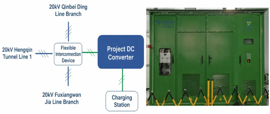
| Guangdong Power Grid 6-Area Interconnection | Equipment efficiency 98.7% (+4%) | Model project for distribution network flexible interconnection |
8. Technical Standards and Compliance
| Standard | Content |
|---|---|
| GB/T 34120 | Energy Storage Grid Integration |
| DL/T 645 | Distribution Network Automation |
| IEC 61850 | Communication Protocol |
9. Delivery and Services
-
Modular factory pre-assembly
-
Rapid on-site deployment
-
Full lifecycle remote operation and maintenance